ترك رسالة
إذا كنت مهتمًا بمنتجاتنا وتريد معرفة المزيد من التفاصيل، فيرجى ترك رسالة هنا، وسوف نقوم بالرد عليك في أقرب وقت ممكن.


The fire truck PTO (Power Take-Off) is a power transmission device that transfers engine power to the fire pump. When the firefighter activates the PTO, mechanical power from the engine is transmitted through the transmission and PTO to the fire pump — this is the core working principle of how a fire fighting truck PTO system operates — enabling the pump to deliver high-pressure, high-flow water or foam without the need for a separate auxiliary engine.
Modern fire trucks typically use side-mounted PTO or full power PTO systems. These offer stable power output, convenient operation, and low maintenance costs, making them an essential component of the fire truck's firefighting system.
 Work")
PTO (Power Take-Off) is a critical component in the fire truck's power system. It is a gear transmission device installed between the engine and the transmission, designed to "divert" a portion of mechanical power from the vehicle's engine or transmission to the fire pump or other auxiliary equipment, without affecting the vehicle's normal driving capability.
The fire truck engine is originally responsible only for driving the wheels. However, once the fire truck arrives at the fire scene, the wheels no longer need power, while the fire pump requires power to draw and pressurize water. The PTO is the device that accomplishes this "power switch."

Power Take-Off (PTO) literally means "power output device."
On a fire truck, it refers to extracting rotational power from the engine flywheel or transmission gears through gear engagement, and delivering it to the fire pump or other auxiliary equipment.
Its name describes its function:
Engine = Power source
PTO = Power distributor
Fire pump = Power consumption end
Therefore, the PTO is the bridge connecting the "power source" and the "firefighting system."
The core reason fire trucks must be equipped with a PTO is that firefighting operations require continuous, stable, high-power output that cannot rely on the vehicle's driving state.
Main reasons:
1. Provides continuous firefighting power
The fire pump needs to run for extended periods during firefighting operations. The PTO allows the engine to continuously drive the fire pump at idle or fixed RPM, ensuring stable water pressure and flow.
2. Improves power utilization efficiency
Without a PTO, a separate auxiliary engine would be required to drive the fire pump, which would increase:
Cost
Maintenance complexity
Risk of failure
Space occupation
The PTO directly utilizes the vehicle's engine power, improving overall efficiency.
3. Supports multiple firefighting systems
Modern industrial fire trucks may include not only water pumps but also:
Foam systems
Dry powder systems
High-pressure water systems
Remote-controlled fire monitors
Without a PTO, there are only two solutions:
Install a separate engine to drive the pump → increases weight, cost, maintenance points, and occupies space
Keep the pump permanently connected to the transmission → pump stops when vehicle stops, unable to pump water on site
The PTO solves both problems at once:
| Mode | PTO Status | Power Destination | Result |
| Driving mode | Disengaged | All to wheels | Normal driving |
| Firefighting mode | Engaged | All to fire pump | Pumping while stationary |
The PTO is essentially a "power distribution and conversion system" that transforms vehicle driving power into firefighting operational power.
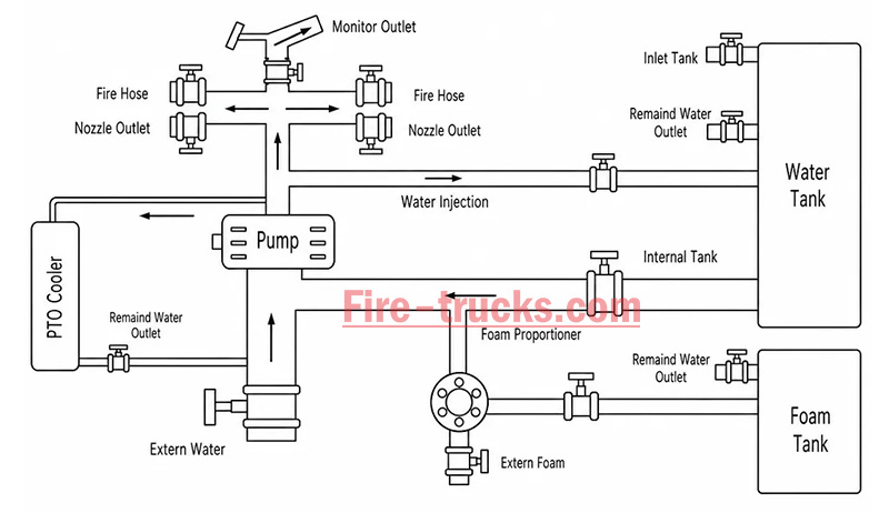
From an engineering perspective, the complete power path is:
Engine → Transmission → PTO → Drive Shaft → Fire Pump → Fire Monitor/Hose System
The PTO's working principle can be summarized in three key stages: power take-off, engagement, and transmission.
The PTO draws power from the engine. Depending on the installation position, the power take-off method differs:
| PTO Type | Installation Position | Power Source | Characteristics |
| Side-mounted PTO | Transmission side | Transmission countershaft gear | Simple structure, lower power (≤50% engine power) |
| Sandwich PTO | Between engine and transmission | Engine flywheel | Full power output, mainstream configuration |
| Split-shaft PTO | Between transmission and driveshaft | Transmission output shaft | High power, allows pumping while driving |
After the driver presses the PTO switch in the cab, the engagement mechanism activates:
| Engagement Method | Working Principle | Common On |
| Electric solenoid control | Electrical signal activates solenoid, pushing shift fork | Mainstream on modern fire trucks |
| Pneumatic control | Compressed air pushes piston, actuating fork | Large fire trucks |
| Manual cable | Mechanical cable directly pulls fork | Older vehicles |
Operation sequence:
Press PTO switch → Solenoid/cylinder actuates → Shift fork pushes sliding gear → Meshes with flywheel or transmission gear → Power connected
After the PTO output shaft begins rotating, power is transmitted through the drive shaft to the fire pump:
PTO output shaft rotates → Drive shaft → Fire pump input shaft → Pump impeller rotates → Water is pressurized and discharged
| Step | Action | Result |
|---|---|---|
| Step 1 | Engine starts, vehicle idling or driving | Engine running, PTO disengaged |
| Step 2 | Arrive at scene, driver presses PTO switch | Driving power disengaged (on some models), PTO gear activated |
| Step 3 | PTO establishes power connection with transmission | Transmission power is diverted to PTO output shaft |
| Step 4 | Drive shaft transmits power to fire pump | Fire pump begins receiving continuous mechanical power |
| Step 5 | Fire pump impeller rotates at high speed | Suction → Pressurization → Delivery to discharge lines → Firefighting |
| Step 6 | System reaches balanced RPM | Stable output, adjustable pressure, flow, and spray pattern |
The fire truck PTO system is a complete power transmission chain, with multiple components working together to transfer engine power to the fire pump. The system can be broken down into six core components:
The engine is the power source of the PTO system and the heart of the entire fire truck.
Function: Generates raw rotational power, driving the flywheel or crankshaft.
Power output: Typically 300–600 HP (depending on chassis model and configuration).
Relationship with PTO: The PTO draws power from the engine flywheel or crankshaft — it is the starting point of power.
Key characteristic: Engine RPM directly affects PTO output speed and the fire pump's water discharge capability. Fire trucks are typically equipped with high-power diesel engines, which not only drive the vehicle but also provide ample power reserve for the fire pump. After PTO engagement, the operator can control pump discharge pressure by adjusting engine RPM.
The transmission is responsible for power delivery and speed matching.
Function: Receives engine power and adjusts speed and torque through different gear combinations.
Relationship with PTO: Side-mounted PTO draws power from internal transmission gears; sandwich PTO is installed at the front of the transmission.
Key characteristic: Transmission gear position does not affect PTO output speed — PTO operates independently of gear selection.
Two power take-off positions:
Transmission side window take-off: PTO mounted on transmission side, drawing power from countershaft or intermediate shaft gears; common on medium-duty fire trucks.
Transmission rear-end take-off (sandwich): PTO installed between engine and transmission, drawing power directly from the flywheel, enabling full power output.
The PTO is the core of the entire system, responsible for "extracting" power from the engine and delivering it to the fire pump.
Function: Extracts power from the engine or transmission and converts it to the speed and torque suitable for the fire pump.
Installation position: Transmission side (side-mounted) or between engine and transmission (sandwich).
Key characteristic: Determines power transmission efficiency, speed matching, and operational convenience.
The drive shaft is the "power bridge" connecting the PTO and the fire pump.
Function: Transmits rotational power from the PTO output shaft to the fire pump input.
Structure: Typically consists of a metal shaft tube, universal joints, and splined connections.
Key characteristic: Must be precisely aligned to avoid vibration; universal joints allow angular compensation.
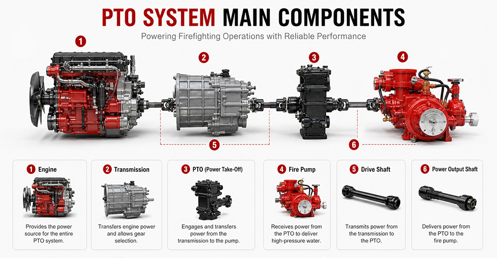
The fire pump is the final load of the PTO system, responsible for converting mechanical energy into water pressure energy.
Function: Receives rotational power from the PTO, drives the impeller to rotate, draws water in, and discharges it under high pressure.
Type: Centrifugal pump (single-stage, two-stage, or multi-stage).
Typical flow rate: 20 L/s – 180 L/s (1,200 – 6,000 L/min).
Typical pressure: 1.0 – 2.5 MPa (10 – 25 bar).
The PTO control system is the "command center" between the driver and the PTO system, responsible for engagement, disengagement, safety protection, and status indication.
Function: Controls PTO engagement and disengagement, monitors system status, and provides safety protection.
Operating location: Cab interior (primary control) and pump panel (auxiliary control).
Control methods: Manual cable, electric solenoid, pneumatic.
Specific control functions:
(1) PTO Engagement Control
The operator presses the PTO switch (electric solenoid/pneumatic) or pulls the lever (manual) in the cab. The control system sends a signal to engage the PTO's internal gears with the power source. After successful engagement is confirmed, an indicator light illuminates, allowing the operator to increase engine RPM.
(2) PTO Disengagement Control
The operator presses the switch again or resets the lever. The control system cuts the signal, and the PTO gears disengage. After disengagement is confirmed, the indicator light turns off.
| PTO Type | Installation Position | Power Source | Power Output | Typical Application |
| Sandwich PTO | Between engine and transmission | Engine flywheel | Full power (≥90%) | Fire pumpers, aerial trucks |
| Split-shaft PTO | Middle of chassis driveshaft | Transmission output shaft | Full power | Large vacuum trucks, airport fire trucks |
| Side-mounted PTO | Transmission side | Transmission gears | Partial power (lower) | Sprinkler trucks, small vacuum trucks |
Sandwich PTO
Advantages: Full power output (≥90%), supports "pumping while driving" (dual-function), high transmission efficiency, easy lubrication.
Disadvantages: Higher cost, complex installation, requires modification to the engine-transmission connection.
Split-shaft PTO
Advantages: Full power output, no additional space required, high reliability, good dynamic balance, can replace auxiliary engine to drive large pumps.
Disadvantages: Requires cutting the original driveshaft, installation position selection must consider driveshaft angle and length compensation.
Side-mounted PTO
Advantages: Low cost, simple installation, can draw power directly from the transmission side.
Disadvantages: Only partial power available, lower output torque, cannot drive high-power fire pumps, mainly used for low-speed, low-power equipment.
 for Fire Trucks")
The process follows a clear mechanical transmission chain:
Engine → PTO → Drive Shaft → Fire Pump → Impeller Rotation → Suction → Pressurization → Fire Monitor
| Factor | Role |
|---|---|
| Centrifugal pump characteristic | When impeller speed is constant, discharge pressure remains naturally stable |
| PTO rigid connection | No slippage or power loss, ensuring continuous stable power input |
| Pressure governor | Automatically detects flow changes and adjusts engine RPM to maintain set pressure |
| Relief valve | Automatically bypasses when pressure exceeds limit, preventing equipment damage |
① Pump speed is determined by engine RPM
Fire pump impeller speed = Engine RPM × PTO ratio. The PTO ratio is fixed (e.g., 1.75:1), so pump speed changes directly with engine RPM.
Calculation formula:
Engine RPM × PTO ratio = Pump speed (RPM)
② Physical relationship between pressure and speed
The pressure generated by a centrifugal pump is proportional to the square of the impeller speed. This physical law means that small changes in RPM cause significant pressure fluctuations.
Speed increases → Centrifugal force increases → Discharge pressure rises
Speed decreases → Centrifugal force decreases → Discharge pressure drops

1. PTO will not engage
Possible causes: Low air pressure (pneumatic type), faulty solenoid, damaged or stuck cable, interlock conditions not met (parking brake not applied, transmission not in neutral).
Solutions: Check air system pressure (must be ≥0.6 MPa); test solenoid; inspect cable; confirm parking brake is applied and transmission is in neutral.
2. PTO engages but pump does not work
Possible causes: PTO clutch failure, broken drive shaft or worn splines, damaged internal gears.
Solutions: Check PTO clutch engagement; inspect drive shaft for breakage or loose connections; disassemble and inspect internal gears.
3. PTO unusual noise
Possible causes: Poor gear meshing or wear, worn bearings, insufficient or degraded lubrication, PTO not fully disengaged.
Solutions: Check gear clearance and tooth wear; inspect bearings; replace with qualified lubricant; confirm PTO is fully disengaged.
4. PTO oil leakage
Possible causes: Worn or deteriorated seals, cracked housing, loose mounting bolts.
Solutions: Replace seals (O-rings, oil seals); inspect housing for cracks; tighten mounting bolts.
5. PTO overheating
Possible causes: Prolonged high-load operation, insufficient or degraded lubricating oil, cooling system failure.
Solutions: Reduce load or shut down for cooling; replace with qualified lubricant; inspect cooling lines.
6. PTO insufficient power
Possible causes: Improper PTO ratio selection, engine RPM set too low, clutch slippage.
Solutions: Confirm PTO ratio matches the fire pump; increase engine RPM to rated operating range; inspect clutch for slippage.
Q1. What does PTO stand for on a fire truck?
PTO stands for Power Take-Off. It is a mechanical system that transfers engine power from the truck's transmission to the fire pump. In simple terms, PTO allows the fire truck's engine to power the pumping system so it can deliver high-pressure water or foam for firefighting operations without needing a separate engine. It is a critical component in industrial and municipal fire trucks.
Q2. Why do fire trucks need a PTO?
Fire trucks need a PTO because it enables the vehicle's main engine to drive the fire pump efficiently. Without a PTO, the fire pump would require a separate engine, which increases cost, weight, and maintenance complexity. PTO systems provide a compact, reliable, and fuel-efficient way to ensure continuous water or foam supply during firefighting operations.
Q3. Can a fire truck operate without a PTO?
Most modern fire trucks cannot operate their pumping system without a PTO because the PTO is responsible for transferring engine power to the fire pump. However, some specialized fire vehicles may use an independent auxiliary engine to drive the pump. These designs are less common due to higher cost, increased maintenance, and lower efficiency compared to PTO-based systems.
Q4. What is the difference between PTO and a fire pump?
The PTO is a power transmission device, while the fire pump is a water or foam pumping system. The PTO delivers mechanical power from the engine to the pump, and the fire pump converts that power into hydraulic pressure to move water or foam. In short, PTO is the "power source connector," and the fire pump is the "firefighting output device."
Q5. How much power can a fire truck PTO provide?
The power output of a fire truck PTO depends on the vehicle design and transmission system. Typically, PTO systems can provide between 50 kW to over 300 kW of mechanical power. Heavy-duty industrial and airport fire trucks often use high-capacity PTO systems capable of supporting large-flow fire pumps and continuous high-pressure operations.
Q6. What are the different types of fire truck PTOs?
There are several types of fire truck PTO systems, including side-mounted PTO, rear-mounted PTO, split shaft PTO, and full power PTO. Side-mounted PTO is commonly used in standard fire trucks, while split shaft and full power PTO systems are used in industrial and airport fire trucks where higher power output and continuous operation are required.
Q7. How do you maintain a fire truck PTO?
PTO maintenance includes regular inspection of lubrication oil levels, checking for leaks, tightening mounting bolts, and ensuring proper alignment of the drive shaft. Operators should also test engagement and disengagement functions regularly. Preventive maintenance is essential to avoid overheating, mechanical wear, and unexpected failure during emergency operations.
Q8. What causes a fire truck PTO to fail?
Common causes of PTO failure include insufficient lubrication, worn gears, misalignment of the drive shaft, overheating, and improper operation by the driver. Electrical or hydraulic control system failures can also prevent PTO engagement. Regular maintenance and correct operating procedures significantly reduce the risk of PTO failure.
Q9. Which PTO is best for industrial fire trucks?
For industrial fire trucks, the best option is usually a split shaft PTO or full power PTO system. These systems can handle high power output, continuous operation, and large-capacity fire pumps. They are widely used in petrochemical plants, refineries, airports, and large industrial facilities where reliable and long-duration firefighting performance is required.
Q10. What should buyers consider when choosing a fire truck PTO?
Buyers should consider engine power compatibility, required fire pump flow rate, vehicle type, and working environment. It is also important to evaluate PTO durability, cooling performance, maintenance accessibility, and compatibility with the chassis. For export projects, compliance with international standards and local regulations should also be taken into account to ensure approval and operational reliability.
PTO (Power Take-Off) is the core system that transfers engine power to the fire pump — it determines whether the entire firefighting system can operate properly.
The fire truck power chain is: Engine → Transmission → PTO → Drive Shaft → Fire Pump → Fire Monitor. Any weak link in this chain affects final firefighting performance.
The primary function of the PTO is to provide stable, continuous mechanical power output, enabling the fire truck to deliver efficient water or foam supply without requiring a separate engine.
Different PTO types (Side-mounted, Rear-mounted, Split shaft, Full power) are suited to different fire truck classes. Industrial fire trucks typically prioritize high-power PTO systems.
PTO performance must match the fire pump flow rate and vehicle chassis, otherwise issues such as insufficient power, unstable pressure, or system overload may occur.
Regular PTO system maintenance (lubrication, tightening, alignment inspection) is key to ensuring reliable fire truck operation, especially in high-intensity industrial applications.
When purchasing industrial fire trucks, buyers should not focus solely on price. PTO power, stability, compatibility, and after-sales support are equally critical factors to evaluate.
For high-risk scenarios such as petrochemical plants, airports, and large industrial parks, Full Power PTO or Split Shaft PTO systems are recommended to ensure continuous operational capability.


قد تكون مهتمًا بالمعلومات التالية
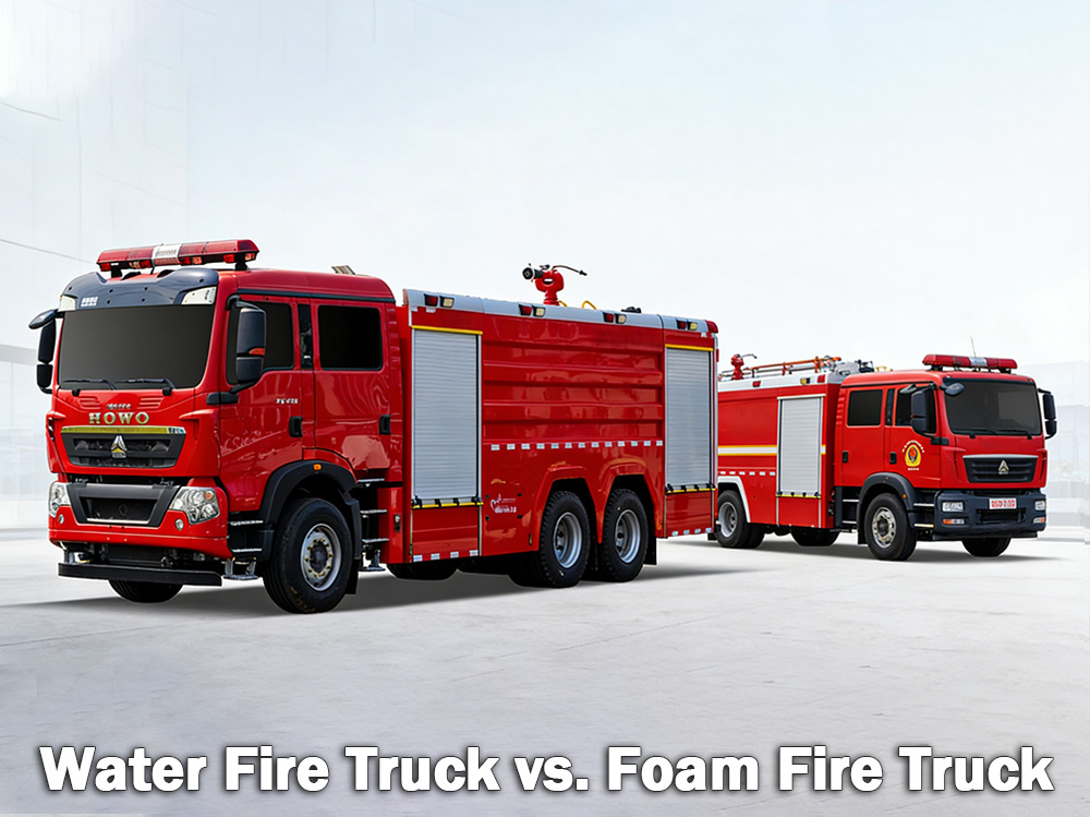
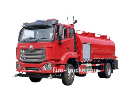
سيارات إطفاء المياه تُستخدم شاحنات إطفاء الحرائق التي تعمل بالرغوة لمكافحة الحرائق العادية التي تشمل الخشب والورق والقماش. أما شاحنات إطفاء الحرائق التي تعمل بالرغوة فتُستخدم لمكافحة حرائق السوائل القابلة للاشتعال مثل البنزين والزيت. ويعتمد اختيار الأنسب على نوع المخاطر الموجودة. أ شاحنة إطفاء مياه تحمل هذه الشاحنة خزان مياه كبير وتعتمد على مضخة ضغط عالٍ لضخ المياه عبر الخراطيم أو مدفع مائي. وهي أكثر أنواع شاحنات الإطفاء شيوعاً في إدارات الإطفاء البلدية والمواقع الصناعية حول العالم. أ شاحنة إطفاء رغوية من ناحية أخرى، صُممت هذه المركبة خصيصًا لحمل وتوزيع رغوة إطفاء الحرائق. عندما لا يكفي الماء وحده لإخماد الحريق بفعالية - كما هو الحال مع حرائق السوائل القابلة للاشتعال أو المواد الكيميائية أو الوقود - تُعد الرغوة الخيار الأمثل. تعمل الرغوة عن طريق تكوين طبقة عازلة فوق النار، مما يقطع الأكسجين ويمنع إعادة اشتعالها. أولاً: ما هي شاحنة إطفاء الحرائق المائية؟ شاحنة إطفاء المياه هي كما يوحي اسمها تمامًا - مركبة مزودة بخزان مياه كبير، ومضخة قوية، وخراطيم أو مدافع لتوصيل المياه إلى مواقع الحرائق. يتسع خزان المياه عادةً لما بين 500 و3000 جالون (ما يقارب 2000 إلى 12000 لتر). تسحب المضخة المياه من الخزان أو من مصدر خارجي مثل صنبور إطفاء أو بحيرة أو بركة، ثم تدفعها عبر الخراطيم تحت ضغط عالٍ. أين تعمل شاحنات إطفاء الحرائق المائية بشكل أفضل؟ تُعد شاحنات إطفاء الحرائق المائية مثالية لـ حرائق الفئة أ والتي تشمل المواد القابلة للاحتراق العادية: الخشب والأخشاب الورق والكرتون القماش والنسيج المطاط والبلاستيك الأعشاب والشجيرات ومواد الغابات إذا كان الحريق يشمل مواد تحترق في منزل أو مستودع أو حقل، فعادةً ما يطفئه الماء. محددات المياه: للماء نقطة ضعف رئيسية. فعند رشه على سوائل مشتعلة كالبنزين والزيت والمواد الكيميائية، يغوص الماء لأنه أثقل من هذه المواد. فيطفو الوقود على السطح ويستمر في الاحتراق. وفي بعض الحالات، قد يتسبب الماء في انتشار الحريق إلى مساحة أوسع. ولذلك، لا يُعدّ الماء وحده فعالاً في إخماد حرائق السوائل القابلة للاشتعال. مواصفات مضخة إطفاء الحريق لشاحنة إطفاء المياه: شاحنة إطفاء المياه جهاز مراقبة الحريق تحديد: ثانياً: ما هي شاحنة إطفاء الحرائق الرغوية؟ شاحنة إطفاء الحرائق بالرغوة هي مركبة متخصصة مصممة لنقل وتوزيع رغوة إطفاء الحرائق. تحمل الشاحنة خزانين منفصلين، أحدهما للماء والآخر لمركز الرغوة. يقوم نظام مزج الرغوة بخلط المكونين بنسبة محددة، عادةً 1% أو 3% أو 6% من مركز الرغوة إلى الماء. ثم يمر هذا المزيج عبر فوهة الرغوة حيث يُضاف الهواء، مما يُنتج طبقة رغوية متمددة ومستقرة. كيف يعمل الرغوة: تُشكّل الرغوة طبقة فوق السائل أو المادة المحترقة. هذه البطانية: يقطع إمداد الأكسجين عن النار يبرد سطح الوقود يمنع تسرب الأبخرة القابلة للاشتعال يمنع اشتعال النار مرة أخرى أين تعمل شاحنات إطفاء الحرائق الرغوية بشكل أفضل؟ تُعد شاحنات إطفاء الحرائق الرغوية ضرورية لـ حرائق الفئة ب والتي تتضمن سوائل قابلة للاشتعال والاحتراق: البنزين والديزل وقود الطائرات والكيروسين الزيت والشحم الكحول والإيثانول المواد الكيميائية الصناعية كما أن الرغوة فعالة أيضاً في بعض أنواع الحرائق من الفئة أ التي يصعب إخمادها بالماء وحده، مثل الحرائق في المستودعات التي تحتوي على بضائع مكدسة أو مرافق تخزين الإطارات. التطبيقات الشائعة: طلب لماذا تعمل الرغوة؟ المطارات تتطلب حرائق وقود الطائرات رغوة؛ فالما...
تفاصيل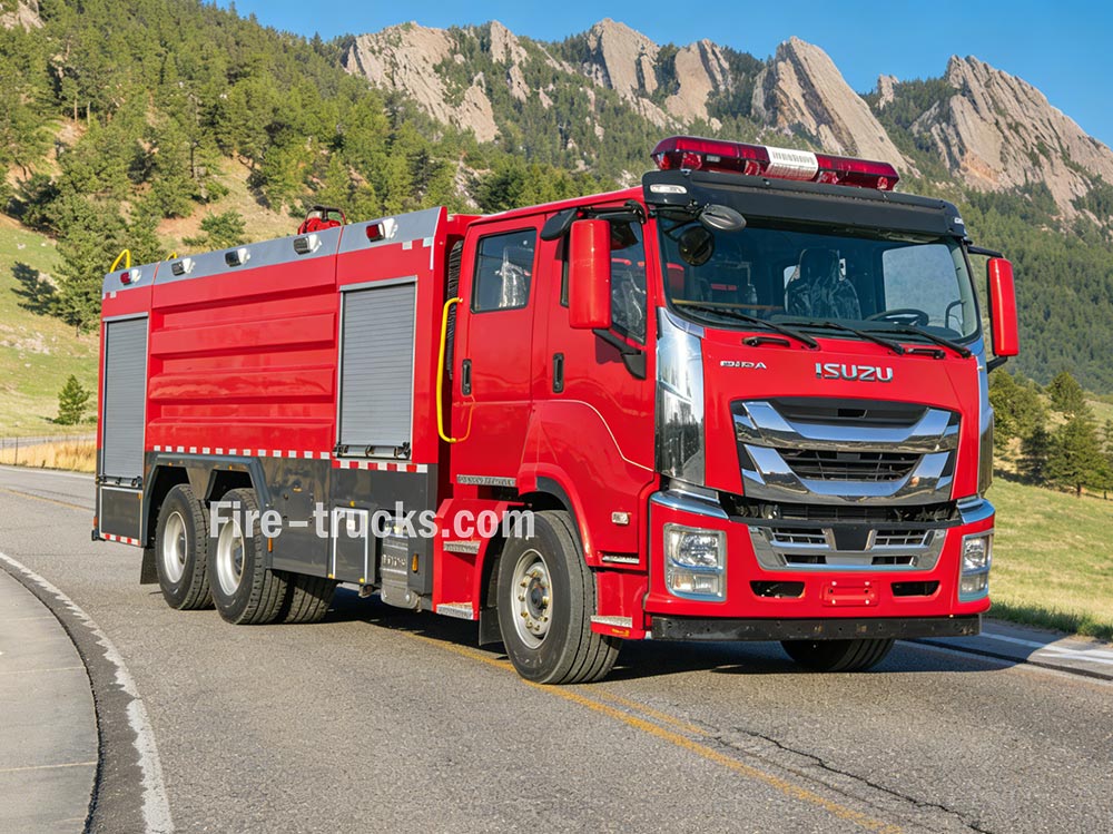
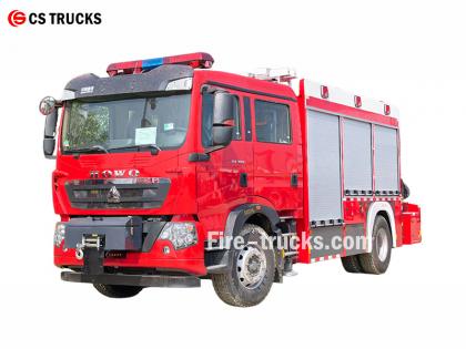
سيارات الإطفاء تعمل فرق الإطفاء من خلال التنسيق بين عدة أنظمة لتوفير المياه، وتوليد الضغط، وإخماد الحرائق. ويساعد فهم هذه المبادئ فرق الإطفاء على العمل بفعالية في حالات الطوارئ. » Ⅰ. كيف تعمل سيارات الإطفاء: ▪ أ. نظام المضخات: قلب إخماد الحرائق: تُعدّ المضخة قلب أي شاحنة إطفاء. تقوم هذه الوحدة عالية الطاقة بسحب الماء من الخزان الموجود على متنها أو من مصدر خارجي، مثل صنبور إطفاء الحريق أو بحيرة أو بركة، ثمّ تضخّه عبر خراطيم تحت ضغط عالٍ. وتُعدّ المضخة الطاردة المركزية أكثر أنواع المضخات استخدامًا، حيث تعتمد على دافع دوّار لضغط الماء وتحريكه. يتحكم رجال الإطفاء في تدفق المياه باستخدام سلسلة من الرافعات والمقاييس الموجودة على لوحة المضخة. ويمكنهم ضبط الضغط حسب الحاجة وتوجيه المياه إلى عدة خراطيم في وقت واحد. نوع المضخة صفات أفضل تطبيق مضخة طرد مركزي أحادية المرحلة تدفق عالٍ، ضغط معتدل خدمات الإطفاء العامة للبلدية مضخة طرد مركزي ثنائية المراحل قابل للتبديل بين قياس الحجم والضغط مبانٍ شاهقة، خراطيم طويلة ممتدة مضخة متعددة المراحل ضغط مرتفع جداً المنشآت الصناعية، أنظمة الرغوة ▪ أهم معايير المضخة: معدل التدفق: 1200 - 6000 لتر في الدقيقة (حسب الطراز) › أقصى ضغط: 1.0 - 2.5 ميجا باسكال (10-25 بار) › وقت التحضير: ≤30 ثانية ▪ ب. خزان المياه ونظام التخزين: › سعة الخزان: من 500 إلى 1500 جالون (ما يقارب 2000 إلى 6000 لتر)، وذلك حسب حجم ونوع المركبة مادة الخزان: فولاذ مقاوم للتآكل أو فولاذ كربوني مطلي › حواجز داخلية: حجرات متعددة بتصميم مضاد للاندفاع للتحكم في حركة المياه أثناء الاستجابة للطوارئ › مدة التعبئة: ≤ 3 دقائق عبر صنبور إطفاء الحريق أو عن طريق السحب مؤشر مستوى الماء: مقياس مرئي على جانب الخزان؛ شاشة عرض اختيارية في الكابينة يتم تصنيع الخزان من مواد مقاومة للتآكل، وعادة ما تكون من الفولاذ المقاوم للصدأ أو الفولاذ الكربوني المطلي، مع ألواح حاجز داخلية تتحكم في تدفق المياه أثناء القيادة في حالات الطوارئ. ▪ ج. أنظمة الخراطيم والفوهات تحمل شاحنات الإطفاء خراطيم متنوعة ذات وظائف مختلفة: خرطوم إطفاء الحريق: قطره من 1.5 إلى 2.5 بوصة - يوصل الماء مباشرة إلى مصدر الحريق › خرطوم الإمداد: قطره من 4 إلى 5 بوصات — ينقل الماء من صنابير الإطفاء أو مضخات المياه الأخرى › خرطوم معزز: قطر صغير ملفوف على بكرة - يستخدم لإخماد الحرائق الصغيرة مثل حرائق الأعشاب أو حرائق المركبات في نهاية الخرطوم، تسمح الفوهة لرجال الإطفاء بالتحكم في تدفق المياه، وضبط الضغط والنمط والاتجاه بناءً على نوع الحريق. ▪ د. جهاز مراقبة الحريق › جهاز مراقبة المياه: يوفر تدفقًا عاليًا من المياه لإخماد الحرائق واسعة النطاق؛ ثابت أو يعمل عن بُعد › جهاز مراقبة المسحوق الجاف: يقوم بإطلاق مسحوق كيميائي جاف لإخماد حرائق السوائل والغازات والحرائق الكهربائية القابلة للاشتعال › جهاز مراقبة متعدد الوظائف: قادر على تفريغ كل من الماء والمسحوق الجاف؛ ويقوم بالتبديل بين الوسائط حسب الحاجة ▪ هـ. نظام التحكم في المحرك، ونظام نقل الحركة، ونظام المضخة نظام المحرك ونقل الحركة ● قدرة المحرك: 300 - 600 حصان — تُستخدم لتشغيل كل من حركة المركبات وأنظمة إخماد الحرائق ● نوع المحرك: محرك ديزل كبير - يضمن أداءً موثوقًا به في شوارع المدينة أو على الطرق الوعرة تحت الحمل الكامل ● مأخذ الطاقة (PTO): يعيد توجيه طاقة المحرك لتشغيل مضخة المياه أو السلم الهوائي أو الأنظمة الهيدروليكية الأخرى لوحة التحكم ● عداد دورات المحرك: يعرض عدد دورا...
تفاصيل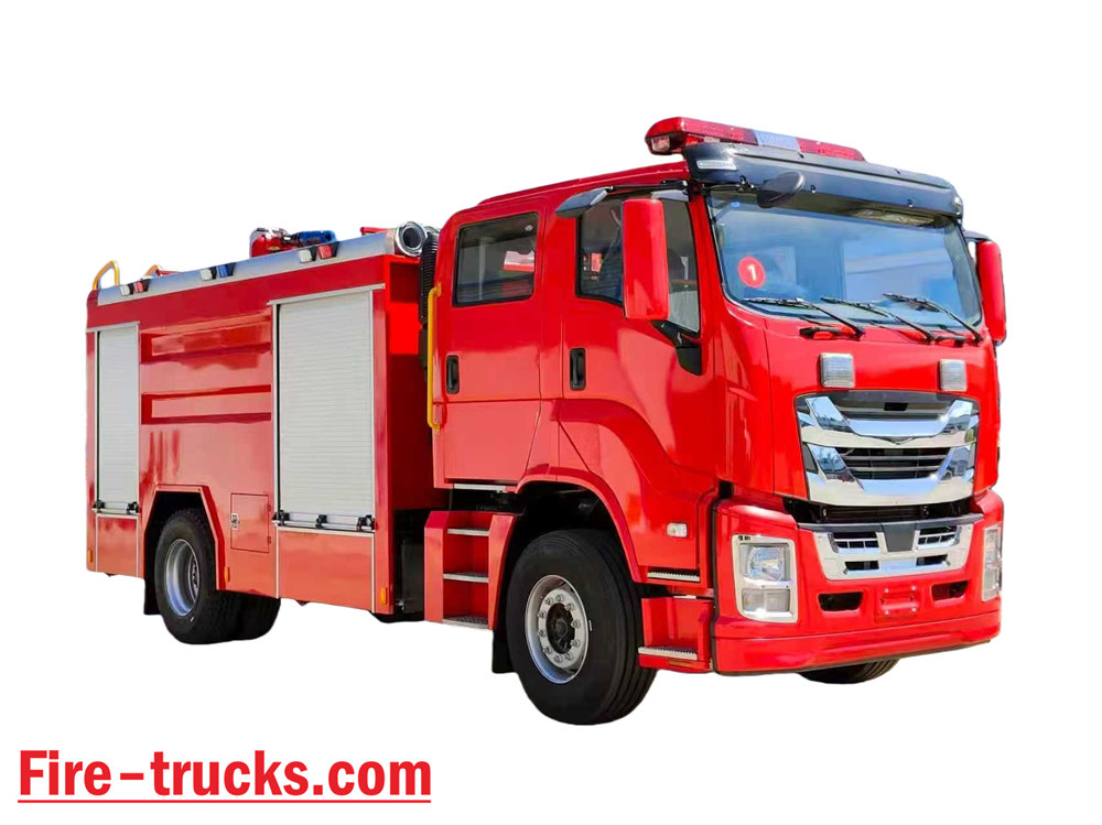
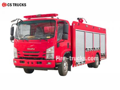
باعتبارها المصنع الأكثر احترافية لشاحنات إطفاء إيسوزو، فإن التصميم الأساسي لشاحنة إطفاء إيسوزو NPR المزودة بنظام رغوة الماء يكمن في دمج نظام إطفاء الرغوة في شاحنة إطفاء مزودة بخزان مياه، لتشكيل جهاز إطفاء متكامل قادر على رش الماء والرغوة معًا. يمكنها إخماد الحرائق بشكل مستقل، وتوصيل خليط الماء أو الرغوة إلى معدات أخرى، وهي مناسبة للعمليات في المناطق القاحلة والتي تعاني من ندرة المياه. ★ تقني مواصفة جميع شاحنات الإطفاء من شركة CS Trucks، مصممة بالكامل وفقًا لمتطلبات العميل. سعة طراز المحرك ماء رغوة مضخة حريق جهاز مراقبة الحريق 2500 لتر إيسوزو 4HK1 / 19 0 حصان 2500 لتر 500 لتر مضخة إطفاء الحريق CB10/40 PL8/32 شاحنة إطفاء رسمية من إيسوزو 2026، هيكل وكابينة رسم هيكل شاحنة إطفاء أصلية لعام 2026 غرض تفاصيل تصميم شاحنات إطفاء إيسوزو التصميم الأساسي يدمج نظام إطفاء رغوي في شاحنة إطفاء مزودة بخزان مياه، مما يشكل مركبة إطفاء ذات قدرة مزدوجة قادرة على إطلاق كل من الماء والرغوة. تشمل الميزات ما يلي: • إخماد الحرائق بشكل مستقل • تزويد المعدات الأخرى بالماء أو خليط الرغوة • مناسب للمناطق القاحلة أو التي تعاني من ندرة المياه، مما يتيح استخدامه لأغراض متعددة. مفهوم التصميم العام صُممت هذه المركبة لتلبية احتياجات مكافحة الحرائق في ورش العمل والمناطق المحيطة بها، مع قدرات مُحسّنة لمكافحة حرائق الزيوت والكهرباء والمواد الصلبة؛ وتتكون من هيكل ومعدات هيكلية متخصصة، مع التركيز على الموثوقية وتعدد الوظائف وسهولة التشغيل. اختيار الهيكل • يستخدم هيكلًا من النوع الثاني متوسط أو ثقيل التحمل ومثبتًا • يُنصح باستخدام نظام الدفع الرباعي لتحسين الحركة والتماسك في التضاريس المعقدة تصميم جديد لعام 2026 لشاحنات إطفاء المياه إيسوزو 700P مكونات النظام الأساسية ونقاط التصميم الرئيسية 1. خزان الماء وخزان سائل الرغوة • المادة: فولاذ مقاوم للصدأ، مقاوم للتآكل • السعة الموصى بها: خزان مياه 3000-5000 لتر، خزان سائل رغوة 300-600 لتر • تحسين الهيكل: تفصل الحواجز الداخلية حجرات الماء والرغوة، ويمكن تحويلها عبر منافذ التوصيل إلى وضع خزان ماء واحد، مما يتيح استخدامها لأغراض متعددة. 2. نظام معايرة الرغوة • يستخدم جهاز مزج الضغط المتوازن (المكون الأساسي) لخلط الماء ومركز الرغوة بدقة بنسب 3% أو 6% • إنتاج مستقر لا يتأثر بتقلبات التدفق أو الضغط، مناسب للمشغلين غير المتخصصين • مزود بمدخل شفط رغوة خارجي لإعادة التعبئة في الموقع 3. نظام التصريف • مضخة حريق: مضخة طرد مركزي متعددة المراحل عالية الكفاءة وموفرة للطاقة، معدل التدفق ≥ 4 0 كم طويل • جهاز مراقبة الحريق: جهاز مراقبة ثنائي الغرض يعمل بالماء/الرغوة، يتم التحكم فيه عن بُعد، مداه ≥ 50 مترًا، وزاوية قابلة للتعديل • يدعم التوصيل بخراطيم الإطفاء وفوهات الرغوة لعمليات مرنة تصميم جديد لشاحنات إطفاء الحرائق الرغوية من إيسوزو NPR لعام 2026 سيناريوهات التطبيق والمزايا حريق تسرب نفطي في ورشة عمل مناسب للغاية؛ تعمل الرغوة على إخماد الحريق بسرعة عن طريق عزل الأكسجين حريق أولي في المعدات الكهربائية يمكن استخدام الرغوة أو المسحوق الجاف المركب (لضمان سلامة العزل الكهربائي). احتراق المواد الصلبة يمكن لجهاز مراقبة المياه أن يطفئ بشكل مباشر وفعال العمليات في بيئات تعاني من ندرة المياه يمكن استخدامها كمركبة دعم لإمدادات المياه، مما يتيح نقل المياه لمسافات طويلة شاحنة إطفاء إيسوزو 4X2 FVR للفلبين سعة 2000 لتر من الماء + 500 لتر من الرغوة غطاء فتحة تفتيش أوروبي عال...
تفاصيل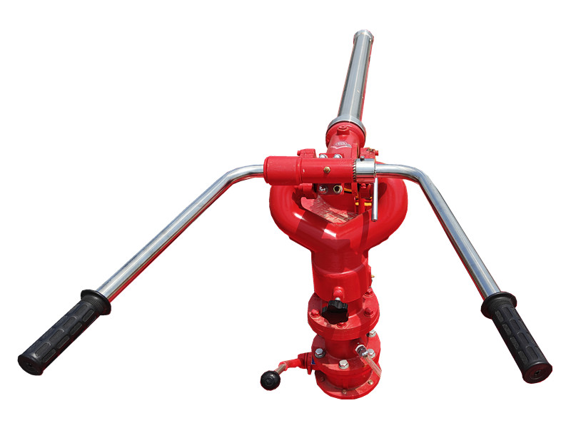
PF5-15 جهاز مراقبة مسحوق جاف ثابت يستخدم هذا المنتج مسحوقًا جافًا كوسيط، ويعتمد على قاعدة ثابتة لضمان رش مستقر. وهو مناسب للمناطق الكيميائية والمستودعات، ويمكنه تغطية سطح الاحتراق بسرعة في المراحل الأولى من الحريق، مما يحسن من كفاءة الإطفاء. ال جهاز مراقبة مسحوق جاف ثابت PF5-15 يتميز بهيكل قوي، وسهل التشغيل، ويمكن ربطه بنظام تحكم آلي للتنشيط عن بعد والرش الدقيق. » Ⅰ. جهاز مراقبة مسحوق جاف ثابت PF5-15 بناء: مميزات جهاز مراقبة المسحوق الجاف الثابت PF5-15: ● يعمل بكامل طاقته؛ ● هيكل بسيط وجديد؛ ● أداء مستقر وصيانة سهلة؛ ● ضغط منخفض عند المدخل؛ ● مزود بصمام تصريف أوتوماتيكي بوظائف قفل أفقية ورأسية؛ ● المادة: سبيكة ألومنيوم مصبوبة بدقة؛ ● رأس المدفع: مصنوع من سبائك الألومنيوم. » Ⅱ. مدفع رغوة PL24 تحديد: نموذج تدفق ( كيلوغرام /س ) يتراوح ( م ) ضغط التشغيل المقدر ( ميجا باسكال ) دوران الملعب ( ° ) الدوران الأفقي ( ° ) الطول × العرض × الارتفاع ( مم ) وزن ( كجم ) PF5-15/40 40 ≥42 0.80 -45 ~ +70 0 ~ 360 980x340x550 28.5 » Ⅲ. تطبيقات المنتج: شاحنة إطفاء مزودة بمدفع مسحوق جاف ثابت من طراز PF5-15 اختبار جهاز مراقبة المسحوق الجاف الثابت PF5-15 يتميز جهاز مراقبة المسحوق الجاف الثابت PF5-15 بمدى رش طويل وتغطية واسعة، ويمكنه تشكيل حاجز إطفاء حريق سريعًا باستخدام المسحوق الجاف. وهو مناسب للمواقع الثابتة مثل المصانع الكيميائية ومستودعات النفط ومناطق التخزين، حيث يوفر قدرات إطفاء حريق مستمرة ومستقرة للمساحات الكبيرة.
تفاصيل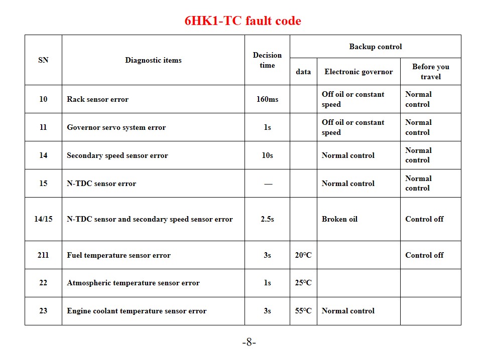
شاحنات إطفاء من طراز إيسوزو 6HK1-TC ، ويسمى أيضًا سيارة إطفاء وإنقاذ من إيسوزو تشخيص أعطال المحرك وحلولها. يستخدم محرك إيسوزو 6HK1-TC نظام التحكم الإلكتروني المتطور لمضخة حقن الوقود TICS، وتتميز وحدة التحكم الإلكترونية (ECU) بخاصية التشخيص الذاتي. عند اكتشاف النظام لعطل، يضيء مؤشر "فحص المحرك" ويتم تخزين رمز العطل. إن فهم تفسير هذه الرموز وحلولها يُسهم بشكل فعال في تحسين كفاءة صيانة المحرك. رموز الأخطاء الشائعة وحلولها رموز أعطال سلسلة P P0101 (انخفاض مستوى دائرة مستشعر تدفق الهواء الشامل) افحص حساس درجة حرارة سائل تبريد المحرك وأسلاكه. تأكد من جهد تغذية الحساس وتوصيله بالأرضي. استبدل وحدة التحكم الإلكترونية أو الحساس إذا لزم الأمر. P0102 (دائرة مستشعر تدفق الهواء الكتلي - حالة عالية) افحص جودة الوقود وحالة الفلتر. نظّف نظام الوقود. افحص منظم ضغط الوقود ومضخة الوقود ودوائر الحقن. P0103 (دائرة مستشعر تدفق الهواء A عالية) افحص دائرة إشارة المستشعر بحثًا عن أي تماس كهربائي. اختبر حالة تشغيل المستشعر. استبدل المستشعر أو وحدة التحكم الإلكترونية إذا لزم الأمر. رموز الأعطال الرقمية 10 (خطأ في مستشعر الرف) افحص مستشعر الرف وأسلاكه. تأكد من نقل الإشارة بشكل طبيعي. 11 (خطأ في نظام المؤازرة لمنظم السرعة) تحقق من حالة تشغيل نظام المؤازرة الخاص بمنظم السرعة. اختبر توصيلات الدائرة ذات الصلة. 14 (خطأ في مستشعر السرعة المساعد) تحقق من موضع تركيب مستشعر السرعة الإضافي. اختبر إشارة خرج المستشعر. 15 (خطأ في مستشعر N-TDC) تحقق من توصيل مستشعر N-TDC تحقق من دقة الإشارة صيانة النظام والتدابير الوقائية SN بنود التشخيص وقت اتخاذ القرار التحكم في النسخ الاحتياطي بيانات منظم إلكتروني قبل السفر 10 خطأ في مستشعر الرف 160 مللي ثانية بدون زيت أو بسرعة ثابتة التحكم الطبيعي 11 خطأ في نظام المؤازرة الخاص بالمنظم 1 ثانية بدون زيت أو بسرعة ثابتة التحكم الطبيعي 14 خطأ في مستشعر السرعة الثانوي 10 ثوانٍ التحكم الطبيعي التحكم الطبيعي 15 خطأ في مستشعر N-TDC — التحكم الطبيعي التحكم الطبيعي 14/15 خطأ في مستشعر N-TDC ومستشعر السرعة الثانوي 2.5 ثانية زيت مكسر إيقاف التشغيل 211 خطأ في مستشعر درجة حرارة الوقود 3 ثوانٍ 20 درجة مئوية إيقاف التشغيل 22 خطأ في مستشعر درجة الحرارة الجوية 1 ثانية 25 درجة مئوية 23 خطأ في مستشعر درجة حرارة سائل تبريد المحرك 3 ثوانٍ 55 درجة مئوية التحكم الطبيعي موصل رقم المحطة إشارة قطر السلك (حزمة مضخة الحقن) SWP 8 أطراف أسود 1 جهد تشغيل مشغل منظم السرعة - 1 2 رينغيت ماليزي 2 دائرة منظم الجهد GND-1 W/1.2 3 موضع الرف المستهدف - 1 U1 2 4 جهد وضع الرف G/1.2 5 دائرة منظم الجهد 5 فولت - 1 Y/1.2 6 مستشعر N الاحتياطي (GND) BR/1.2 7 مستشعر N الاحتياطي (SIG) 0/1.2 8 اسحب لأسفل ب/1.2 SWP6- المحطات أسود ز جهد تشغيل مشغل منظم السرعة - 2 R/1.2 10 موضع الرف المستهدف - 2 لتر/1.2 11 دائرة منظم السرعة GND-2 W/1.2 12 دائرة منظم الجهد SIG-GND BR/1.2 13 دائرة منظم الجهد 5 فولت - 2 Y/1.2 SWP 3- المحطات أسود 14 منزل معطل W1.2 15 ملف فرعي (غير مستخدم) BY/1.2 الصيانة الدورية قم بتغيير زيت المحرك وفقًا للجدول الزمني المحدد (بناءً على عدد الكيلومترات ومتطلبات درجة الحرارة) استبدل ثلاثة فلاتر (فلتر الديزل، فلتر الزيت، وفلتر الهواء). استخدم ديزل مصمم لتحمل درجات الحرارة المحلية مواصفات التشغيل قم بتسخين المحرك قبل تشغيله وهو بارد (خاصة في فصل الشتاء). حافظ على نظام التبريد في فصل الصيف لمنع ارت...
تفاصيل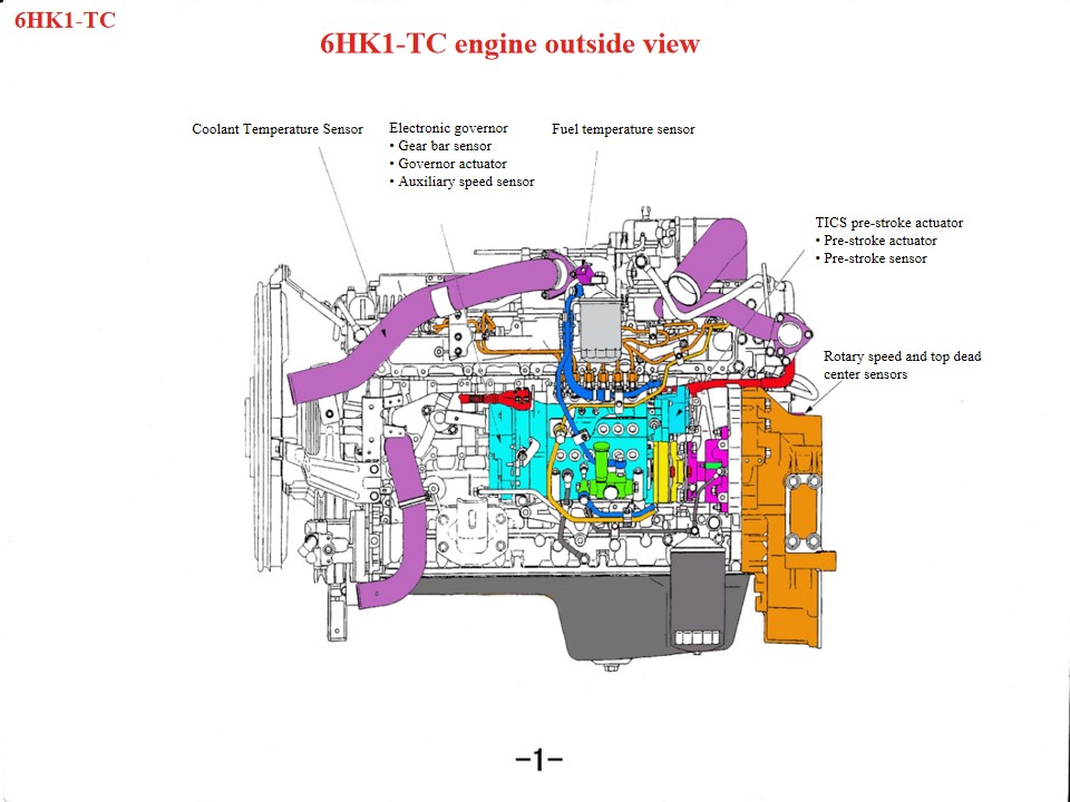
مركبات إطفاء وإنقاذ من طراز إيسوزو 6HK1 ، ويسمى أيضًا شاحنة إطفاء من نوع إيسوزو ، في حالة ارتفاع درجة حرارة محرك شاحنة إطفاء وإنقاذ من طراز إيسوزو، يجب فحص المناطق التالية أولاً: 1. نظام التبريد: يمكن أن تساهم مشاكل مثل المروحة التالفة، أو الرادياتير المسدود، أو منظم الحرارة التالف، أو عدم كفاية سائل التبريد في ارتفاع درجة حرارة المحرك. 2. جودة وكمية الزيت: يمكن أن تتسبب جودة الزيت الرديئة أو عدم كفاية الزيت أيضًا في ارتفاع درجة حرارة المحرك. 3. يمكن أن تتسبب الأعطال الميكانيكية مثل انفجار الأسطوانة، أو تشققات بطانة الأسطوانة، أو تشققات بطانة الأسطوانة في حدوث هذه الظاهرة. باعتباره محرك ديزل عالي الأداء، يتطلب محرك إيسوزو 6HK1 التزامًا صارمًا بالمواصفات الفنية للصيانة. وفيما يلي النقاط الرئيسية: 1. فهم الهيكل ومواصفات التفكيك والتركيب آلية عمود المرفق وذراع التوصيل يتميز غلاف الأسطوانة بتصميم غير محكم، مما يتطلب أدوات خاصة لمنعه من السقوط أثناء الفك والتركيب. الخلوص القياسي يتراوح بين 0.122 و0.156 مم. يتميز القطر الخارجي للمكبس بتفاوت دقيق (114.894–114.909 مم). أثناء التركيب، انتبه إلى اتجاه فتحة حلقة المكبس وضبط "المسافات الثلاث" (المسافة الأمامية، والمسافة الجانبية، والمسافة الخلفية). علبة المرافق السفلية عبارة عن هيكل من قطعة واحدة ويجب رفعها أثناء الصيانة لمنع التشوه. محاذاة نظام التوقيت أثناء تجميع علبة التروس، يجب محاذاة علامات ترس عمود المرفق والترس الوسيط. يجب أن تكون علامة عمود الكامات B مستوية مع سطح رأس الأسطوانة. يجب أن يكون المحرك في أعلى نقطة ميتة في شوط الضغط على الأسطوانة الأولى. عند تركيب مضخة حقن الوقود، قم بمحاذاة مؤشر التوقيت مع النقطة S الموجودة على الموصل، وقم بمحاذاة علامة تقدم الحقن مع مؤشر جسم المضخة. • يقوم محرك التيار المستمر الخطي بدفع الملف لأعلى ولأسفل تحت إشارة خرج وحدة التحكم. • ينقل ذراع التوصيل المثبت على مجموعة الملف حركة الملف لأعلى ولأسفل إلى كتلة التوصيل، المثبتة بدورها في نهاية الرف. وبدفعة من كتلة التوصيل، يتحرك الرف يمينًا ويسارًا لتغيير كمية الوقود المحقون. فعندما تتحرك مجموعة الملف لأعلى، يدفع الذراع الرف لزيادة كمية الوقود المحقون؛ وعلى العكس، عندما تتحرك مجموعة الملف لأسفل، يتحرك الرف لتقليل كمية الوقود المحقون. وتتمثل وظيفة الذراع في تحويل الحركة الرأسية إلى حركة الرف الرأسية. • تُثبّت كتلة النحاس على الجزء العلوي من كتلة التوصيل لتشكيل مستشعر الرف. يكشف مستشعر الرف عن شوط الرف ويرسل هذه القيمة إلى وحدة التحكم، ما يسمح بمقارنة شوط الرف الفعلي مع شوط الرف المستهدف باستمرار حتى يقترب الفرق بينهما من الصفر. هذه العملية بالغة الأهمية للتحكم في الدقة والاستجابة. 2. نقاط الصيانة الرئيسية للنظام نظام التشحيم والتبريد فترة تغيير الزيت: الزيت المعدني: كل 5000 كيلومتر أو ستة أشهر؛ الزيت الاصطناعي: 8000-10000 كيلومتر. يتميز مدخل ماء التبريد بتصميم متدرج، ويتطلب فكه بالتسلسل لأغراض الصيانة. يجب تغيير سائل التبريد كل سنتين أو 40,000 كيلومتر. نظام سحب الوقود والهواء استبدل فلتر الديزل كل 20,000 كيلومتر أو عند إضاءة ضوء التحذير. افحص فلتر الهواء كل 15,000 كيلومتر. يتطلب نظام الوقود تنظيفًا منتظمًا لمنع الشوائب من التأثير على دقة الحقن. 3. إجراءات الصيانة والاحتياطات إعداد الأدوات والبيانات استخدم مفتاح عزم الدوران لربط البراغي (مثل براغي دعامة مضخة الحقن) وفقًا لمواصفات الدليل. قبل إجراء الإصلاح، راجع "دليل خدمة الم...
تفاصيل
الرجاء المتابعة، والاطلاع على آخر المستجدات، والاشتراك، ونرحب بآرائكم.

 شبكة IPv6 مدعومة

 العربية
 English
 français
 Deutsch
 русский
 italiano
 español
 português
 Nederlands
 日本語
日本語 한국의
한국의 Türkçe
 Melayu
 ไทย
ไทย Tiếng Việt
 Indonesia
  中文
中文 қазақ
қазақ Filipino
 မြန်မာ
 српски