ترك رسالة
إذا كنت مهتمًا بمنتجاتنا وتريد معرفة المزيد من التفاصيل، فيرجى ترك رسالة هنا، وسوف نقوم بالرد عليك في أقرب وقت ممكن.


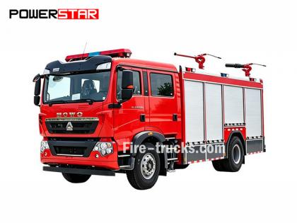
دليل صيانة محرك شاحنة إطفاء إيسوزو 4HK1-TC، والذي يُسمى أيضًا دليل إصلاح المحرك الخاص بـ سيارة إطفاء من نوع إيسوزو أو كتاب المهندس مركبة إطفاء حرائق من نوع إيسوزو .
يُعد محرك إيسوزو 4HK1-TC لشاحنات الإطفاء محرك ديزل عالي الأداء يُستخدم على نطاق واسع في شاحنات الإطفاء، ويشتهر بموثوقيته ومتانته وكفاءته العالية. ولضمان التشغيل المستقر للمحرك على المدى الطويل، تُعد الصيانة والإصلاح الدوريان ضروريين. ستُقدم هذه المقالة عرضًا موجزًا للمحتويات الرئيسية لدليل صيانة محرك إيسوزو 4HK1-TC لشاحنات الإطفاء، وذلك لمساعدة فنيي الصيانة على فهمه وتشغيله بشكل أفضل.
1. نظرة عامة على المحرك
محرك 4HK1-TC هو محرك ديزل رباعي الأسطوانات مزود بشاحن توربيني، بسعة 5.2 لتر وقوة قصوى تبلغ 190 حصانًا. يستخدم المحرك نظام حقن وقود متطور بتقنية السكك الحديدية المشتركة ووحدة تحكم إلكترونية (ECU) لتحقيق كفاءة أعلى في استهلاك الوقود وانبعاثات أقل.
2. الصيانة اليومية
تُعدّ الصيانة اليومية أساسًا لضمان التشغيل السليم للمحرك. ويُفصّل دليل الصيانة بنود الفحص اليومي، بما في ذلك فحص مستوى الزيت وسائل التبريد، وتنظيف أو استبدال فلتر الهواء، واستبدال فلتر الوقود، وما إلى ذلك. بالإضافة إلى ذلك، يُقدّم الدليل توصيات بشأن الاستبدال الدوري لزيت المحرك وفلتر الزيت، عادةً كل 5000 كيلومتر أو كل 6 أشهر.
3. تشخيص الأعطال
يحتوي دليل الصيانة على عملية تشخيص أعطال مفصلة لمساعدة فنيي الصيانة على تحديد المشكلات وحلها بسرعة. يسرد الدليل رموز الأعطال الشائعة ومعانيها، ويقدم الحلول المناسبة لها. على سبيل المثال، إذا كان المحرك يعاني من ضعف في الأداء، فسيرشد الدليل فنيي الصيانة إلى فحص نظام الوقود، والشاحن التوربيني، ونظام العادم، وما إلى ذلك.
4. الإصلاح الشامل واستبدال الأجزاء
بالنسبة للمحركات التي تحتاج إلى إصلاح شامل أو استبدال أجزاء، يوفر دليل الصيانة خطوات واحتياطات مفصلة. على سبيل المثال، عند استبدال مكونات رئيسية مثل حلقات المكابس، وأدلة الصمامات، والمحامل، يوضح الدليل بالتفصيل خطوات الفك والتركيب، بالإضافة إلى الأدوات المطلوبة ومواصفات عزم الدوران.
5. احتياطات السلامة
يُولي دليل الصيانة أهمية خاصة للتشغيل الآمن. قبل إجراء أي عملية صيانة، يجب التأكد من تبريد المحرك تمامًا وفصل مصدر الطاقة. بالإضافة إلى ذلك، يُقدم الدليل توصيات بشأن استخدام معدات الوقاية الشخصية، مثل القفازات والنظارات الواقية والملابس الواقية.
القسم 1أ
نظام التحكم في المحرك
جدول المحتويات
صفحة
[if supportFields]> جدول المحتويات \h \z \t "1A,1,1A-,2"
نظام التحكم في المحرك
[if supportFields]>
4
[if gte mso 9]>
احتياطات
[if supportFields]>
4
[if gte mso 9]>
الوظيفة ومبدأ العمل
[if supportFields]>
5
[if gte mso 9]>
مخطط تكوين الأجزاء
[if supportFields]>
21
[if gte mso 9]>
مخطط الدائرة
[if supportFields]>
25
[if gte mso 9]>
كيفية تشخيص العطل
[if supportFields]>
42
[if gte mso 9]>
إجراءات تشخيص الأعطال من خلال جهاز تشخيص الأعطال
[if supportFields]>
48
[if gte mso 9]>
نظرة عامة على الفحص الوظيفي
[if supportFields]>
50
[if gte mso 9]>
سؤال
[if supportFields]>
51
[if gte mso 9]>
فحص نظام التحكم في المحرك
[if supportFields]>
53
[if gte mso 9]>
قائمة بيانات جهاز تشخيص الأعطال
[if supportFields]>
55
[if gte mso 9]>
محتويات قائمة بيانات جهاز تشخيص الأعطال
[if supportFields]>
58
[if gte mso 9]>
مخرج جهاز تشخيص الأعطال
[if supportFields]>
64
[if gte mso 9]>
فشل بدء تشغيل جهاز تشخيص الأعطال
[if supportFields]>
65
[if gte mso 9]>
فشل الاتصال بجهاز تشخيص الأعطال (مرجع)
[if supportFields]>
67
[if gte mso 9]>
فشل الاتصال مع وحدة التحكم الإلكترونية (المرجع)
[if supportFields]>
71
[if gte mso 9]>
تأكيد بدء تشغيل النظام
[if supportFields]>
74
[if gte mso 9]>
تأكيد نظام الدائرة الكهربائية لإضاءة مؤشر عطل المحرك
[if supportFields]>
77
[if gte mso 9]>
مؤشر عطل المحرك يومض، تأكيد نظام الدائرة الكهربائية
[if supportFields]>
78
[if gte mso 9]>
فحص نظام التحكم في إعادة تدوير غاز العادم (EGR)
[if supportFields]>
80
[if gte mso 9]>
فحص نظام التحكم في التسخين
[if supportFields]>
84
[if gte mso 9]>
فحص نظام التحكم في تقييد مدخل الهواء/مكابح العادم
[if supportFields]>
87
[if gte mso 9]>
نظرة عامة على رموز الأعطال التشخيصية (DTC)
[if supportFields]>
92
[if gte mso 9]>
DTC P0016 (رمز الفلاش 16)
[if supportFields]>
95
[if gte mso 9]>
رمز العطل P0087 (رمز الوميض 225)
[if supportFields]>
97
[if gte mso 9]>
رمز الخطأ التشخيصي P0088 (رمز الفلاش 118)
[if supportFields]>
103
[if gte mso 9]>
رمز الخطأ التشخيصي P0089 (رمز الفلاش 151)
[if supportFields]>
109
[if gte mso 9]>
DTC P0091، P0092 (رمز الفلاش 247)
[if supportFields]>
112
[if gte mso 9]>
رمز الخطأ التشخيصي P0093 (رمز الفلاش 227)
[if supportFields]>
116
[if gte mso 9]>
DTC P0107، P0108 (رمز الفلاش 32)
[if supportFields]>
122
[if gte mso 9]>
DTC P0112، P0113 (رمز الفلاش 22)
[if supportFields]>
127
[if gte mso 9]>
DTC P0117، P0118 (رمز الفلاش 23)
[if supportFields]>
132
[if gte mso 9]>
DTC P0122، P0123 (رمز الفلاش 43)
[if supportFields]>
137
[if gte mso 9]>
DTC P0182، P0183 (رمز الفلاش 211)
[if supportFields]>
142
[if gte mso 9]>
DTC P0192، P0193 (رمز الفلاش 245)
[if supportFields]>
147
[if gte mso 9]>
[if supportFields]> رموز الأعطال التشخيصية P0201، P0202، P0203، P0204 (رموز الفلاش 271، 272، 273، 274)................................................... 1A-157
رمز العطل P0217 (رمز الوميض 542)...................................................................................................... 1A-170
رمز العطل P0219 (رمز الوميض 543)...................................................................................................... 1A-172
رمز العطل P0234 (رمز الوميض 42)........................................................................................................ 1A-175
رمز العطل P0299 (رمز الوميض 65)........................................................................................................ 1A-178
رمز العطل P0335 (رمز الوميض 15)........................................................................................................ 1A-182
رمز العطل P0336 (رمز الوميض 15).......................................................................................... 1A-187
رمز العطل P0340 (رمز الوميض 14)........................................................................................................ 1A-190
رمز العطل P0341 (رمز الوميض 14).......................................................................................... 1A-195
رمز العطل P0380 (رمز الوميض 66)........................................................................................................ 1A-198
رمز العطل P0381 (رمز الوميض 67)........................................................................................................ 1A-201
رمز العطل P0404 (رمز الوميض 45)........................................................................................................ 1A-205
رمز العطل P0409 (رمز الوميض 44)........................................................................................................ 1A-208
رمز العطل P0477، P0478 (رمز الوميض 46)............................................................................................. 1A-212
رمز العطل P0500 (رمز الوميض 25)........................................................................................................ 1A-216
رمز العطل P0502، P0503 (رمز الوميض 25)............................................................................................. 1A-218
رمز العطل P0563 (رمز الوميض 35).......................................................................................... 1A-223
رمز العطل P0601 (رمز الوميض 53).......................................................................................... 1A-225
رمز العطل P0602 (رمز الوميض 154)...................................................................................................... 1A-226
رموز الأعطال التشخيصية P0604، P0606، P060B (رموز الوميض 153، 51، 36).................................................................... 1A-228
رمز العطل P0641 (رمز الوميض 55).......................................................................................... 1A-230
رمز العطل P0650 (رمز الوميض 77)........................................................................................................ 1A-233
رمز العطل P0651 (رمز الوميض 56)........................................................................................................ 1A-237
رمز العطل P0685، P0687 (رمز الوميض 416)........................................................................................... 1A-241
رمز العطل P0697 (رمز الوميض 57)........................................................................................................ 1A-245
رمز العطل P1093 (رمز الوميض 227)...................................................................................................... 1A-248
رمز العطل P1261، P1262 (رمز الوميض 34)............................................................................................. 1A-253
رمز العطل P1404 (رمز الوميض 45)........................................................................................................ 1A-255
رمز العطل P1621 (رمز الوميض 54)........................................................................................................ 1A-257
رمز العطل P2122، P2123 (رمز الوميض 121)........................................................................................... 1A-258
رمز العطل P2127، P2128 (رمز الوميض 122)........................................................................................... 1A-264
رمز العطل P2138 (رمز الوميض 124)...................................................................................................... 1A-270
رمز العطل P2146، P2149 (رمز الوميض 158)........................................................................................... 1A-273
رمز العطل P2228، P2229 (رمز الوميض 71)............................................................................................. 1A-279
رمز العطل P253A (رمز الوميض 28)....................................................................................................... 1A-284
رمز العطل P256A (رمز الوميض 31)....................................................................................................... 1A-287
رمز العطل التشخيصي U0073 (رمز الوميض 84)....................................................................................................... 1A-291
تشخيص الأعراض................................................................................................................... 1A-296
الظواهر: التقطع ........................................................................................... 1A-297
العرض: صعوبة في التشغيل.......................................................................................... 1A-300
الظواهر: تذبذب في سرعة المحرك، أو عدم استقرار دورانه في وضع الخمول، أو توقف المحرك.................................................................... 1A-303
الظواهر: سرعة دوران عالية في وضع الخمول.................................................................................................... 1A-306
العرض: توقف طارئ......................................................................................................... 1A-307
العرض: تغيير طارئ..................................................................................................... 1A-309
الأعراض: انخفاض الطاقة، أو فشل التسارع، أو تأخر الاستجابة........................................................... 1A-311
الظواهر: تشغيل متقطع، عطل في التسارع................................................................... 1A-314
العرض: ضوضاء الاحتراق...................................................................................................... 1A-316
العرض: انخفاض كفاءة استهلاك الوقود.................................................................................... 1A-317
الظواهر: دخان أسود من غازات العادم................................................................................... 1A-319
العرض: دخان أبيض من غاز العادم.................................................................................. 1A-321
معلمات المستشعر الرئيسية.............................................................................................................. 1A-323
أدوات خاصة............................................................................................................................ 1A-325
البرنامج................................................................................................................ 1A-326
قاعدة البرمجة...................................................................................................................... 1A-326
البرنامج................................................................................................................ 1A-326
شرح مضخة الحقن.............................................................................................................. 1A-328
التعديل.............................................................................................................................. 1A-328
استخدام أدوات اختبار الدوائر
في حالة التشخيص وفقًا لبرنامج التشخيص، لا تستخدم مصباح الاختبار لتشخيص النظام الكهربائي لمجموعة نقل الحركة إلا إذا نُص على خلاف ذلك. في حال استخدام طرف المجس لبرنامج التشخيص، يُرجى استخدام طقم محول اختبار الطرف 5-8840-2835-0.
المكونات الكهربائية المتوفرة في السوق
المكونات الكهربائية المتوفرة في السوق هي تلك التي يتم شراؤها من السوق لتركيبها في المركبة. ونظرًا لعدم أخذ هذه المكونات في الاعتبار أثناء تصميم المركبة، يُرجى الانتباه إليها عند استخدامها.
حذر:
يجب توصيل الطاقة والأرضي للمكونات الكهربائية المتوفرة في السوق بالدائرة بغض النظر عن دائرة نظام التحكم الكهربائي.
على الرغم من إمكانية استخدام المكونات الكهربائية المتوفرة في السوق، إلا أنها قد تتسبب في عطل وظيفي في نظام التحكم الكهربائي في بعض الحالات. ويشمل ذلك الأجهزة غير المتصلة بالنظام الكهربائي، مثل الهاتف المحمول والراديو. لذا، عند تشخيص نظام نقل الحركة، تحقق أولاً من وجود هذه المكونات الكهربائية المتوفرة في السوق. إذا كانت موجودة، فقم بإزالتها من السيارة. إذا استمر العطل بعد إزالة المكونات، فاتبع الخطوات العامة للتشخيص.
الضرر الناتج عن التفريغ الكهروستاتيكي
نظرًا لأن المكونات الإلكترونية في نظام التحكم الكهربائي تعمل بجهد منخفض للغاية، فإنها عرضة للتلف بسبب التفريغ الكهروستاتيكي. تتلف بعض المكونات الإلكترونية بفعل الكهرباء الساكنة التي تقل عن 100 فولت، وهي قيمة غير محسوسة للبشر. يتطلب التفريغ الكهروستاتيكي الذي يمكن للبشر الشعور به جهدًا يصل إلى 4000 فولت. في كثير من الحالات، يحمل الإنسان الكهرباء الساكنة، حيث يُعد الاحتكاك والحث الكهربائي من أكثر الطرق شيوعًا لنقلها.
● عندما يتحرك الإنسان من جانب إلى آخر على المقعد، فإنه سيولد الكهرباء الاحتكاكية.
● عندما يكون الشخص الذي يرتدي الأحذية العازلة بالقرب من جسم مشحون كهربائيًا، يحدث الحث الكهروستاتيكي لحظة ملامسة الإنسان للأرض. ويتكهرب الإنسان عندما تتلاقى الشحنات ذات القطبية المتشابهة مع الشحنات ذات القطبية المعاكسة. ونظرًا لأن الكهرباء الساكنة قد تُسبب تلفًا، يجب التعامل بحذر مع الأجزاء الإلكترونية واختبارها.
حذر:
اتبع القواعد التالية لمنع الضرر الناتج عن التفريغ الكهروستاتيكي:
● لا تلمس دبابيس الاتصال الطرفية لوحدة التحكم الإلكترونية والأجزاء الإلكترونية الملحومة باللوحة الخلفية لدائرة وحدة التحكم الإلكترونية.
● لا تقم بفك تغليف الحدائق إلا بعد الانتهاء من تجهيز تركيب الأجزاء.
● قم بتوصيل العبوة والأرضي العادي للمركبة قبل إخراج الأجزاء من العبوة.
● في حالة التحرك من جانب إلى آخر على المقعد، أو الجلوس من وضعية الوقوف أو تشغيل الجزء أثناء التحرك على مسافة معينة، تأكد من لمس الأرض العادية قبل تركيب الجزء.
نظام التحكم في المحرك (السكك المشتركة)
نظرة عامة على النظام وتفاصيله
نظام التحكم في المحرك هو نظام التحكم الكهربائي الذي يضبط المحرك للوصول إلى حالة الاحتراق المثلى وفقًا لظروف القيادة. ويتكون من الأجزاء التالية:
● نظام حقن الوقود الذي يتم التحكم فيه إلكترونياً (من نوع السكة المشتركة)
● إعادة تدوير غاز العادم
إلى جانب ذلك، يتضمن نظام التحكم في المحرك وظائف التحكم التالية.
● نظام التحكم في التسخين
● خرج دوران المحرك
● وظيفة التواصل والتشخيص الذاتي
[endif]
[if gte vml 1]>
نظام حقن الوقود الذي يتم التحكم فيه إلكترونياً (من نوع السكة المشتركة)
يُزوَّد نظام الحقن المباشر للوقود (السكك المشتركة) بحجرة ضغط وحاقن. صُممت حجرة الضغط لتخزين الوقود المضغوط، وتُسمى بالسكك المشتركة؛ أما الحاقن، فيحتوي على صمام لولبي للتحكم الإلكتروني لحقن الوقود المضغوط في غرفة الاحتراق. وبما أن التحكم في الحقن (ضغط الحقن، ومعدل الحقن، ومدة الحقن) يتم بواسطة وحدة التحكم الإلكترونية (ECM)، فإن نظام الحقن المباشر للوقود يسمح بالتحكم المستقل في سرعة المحرك وحمله. حتى عند انخفاض سرعة المحرك، يُمكن الحفاظ على ضغط حقن ثابت، مما يُقلل بشكل كبير من انبعاث الدخان الأسود عند بدء تشغيل محرك الديزل وتسارعه. من خلال هذا التحكم، يصبح غاز العادم أنظف، ويقل حجمه، ويزداد ناتج الطاقة.
التحكم في حجم الحقن
يتحكم في لفات الحاقن وفقًا للإشارة التي تم الحصول عليها من سرعة المحرك وفتح دواسة الوقود، وبالتالي يتحكم في حجم حقن الوقود لتحقيق أفضل حجم.
التحكم في ضغط الحقن
للسماح بحقن الوقود بضغط عالٍ حتى مع انخفاض سرعة المحرك، يجب التحكم في ضغط الوقود داخل سكة الوقود المشتركة. يتم تحديد الضغط المناسب في سكة الوقود المشتركة بناءً على سرعة المحرك وحجم حقن الوقود، ثم يتم ضخ الكمية المناسبة من الوقود عبر مضخة التحكم في الحقن وتغذيتها إلى سكة الوقود المشتركة تحت الضغط المطلوب.
التحكم في وقت الحقن
يقوم هذا النظام باستبدال وظيفة التوقيت ويحسب وقت حقن الوقود المناسب وفقًا لسرعة المحرك وحجم الحقن، ثم يتحكم في الحاقن.
التحكم في معدل الحقن
لتحسين كفاءة احتراق الأسطوانة، يتم حقن كمية قليلة من الوقود (الحقن المسبق) للاشتعال. بعد الاشتعال، يتم إجراء الحقن الثاني (الحقن الرئيسي). يتم التحكم في وقت الحقن وحجمه من خلال الحاقن (ملف الحاقن).
 [endif]
نظام الوقود
يتكون نظام الحقن المباشر للوقود من نظامين لضغط الوقود.
● خط مدخل الضغط المنخفض: بين خزان الوقود ومضخة الحقن
● خط الضغط العالي: بين مضخة الحقن والحاقن
يُسحب الوقود من خزان الوقود إلى مضخة الحقن، ثم يُضخّ داخل المضخة لتزويد نظام الحقن المباشر (السكك المشتركة). عند هذه النقطة، تقوم الإشارة من وحدة التحكم الإلكترونية (ECM) بالتحكم في صمام التحكم في السحب (منظم ضغط السكة المشتركة) للتحكم في حجم الوقود المورد إلى السكة المشتركة.
مخطط نظام الوقود
[if gte vml 1]>
|
مفتاح 1. نظام الحقن المباشر للوقود (السكك الحديدية المشتركة) 2. صمام تحديد الضغط 3. أنبوب إرجاع الحاقن 4. حاقن الوقود 5. أنبوب إرجاع الوقود 6. أنبوب إمداد الوقود |
7. خزان الوقود 8. صمام التنفس 9. مضخة التشغيل 10. فلتر الوقود (مع فاصل الزيت عن الماء) 11. صمام الإرجاع 12. مضخة حقن الوقود |
نظام إعادة تدوير غاز العادم (إعادة تدوير غاز العادم)
يقوم نظام إعادة تدوير غازات العادم (EGR) بإعادة تدوير جزء من غازات العادم إلى مشعب السحب، مما يقلل من انبعاثات أكاسيد النيتروجين (NOx). يُسهم هذا النظام في تحسين أداء السيارة وتقليل انبعاثات غازات العادم. يتحكم تيار التحكم الصادر من نظام EGR في عمل الصمام اللولبي، وبالتالي يتحكم في رفع صمام EGR. بالإضافة إلى ذلك، يستشعر هذا النظام رفع الصمام الفعلي باستخدام مستشعر موضع EGR، مما يتيح تحكمًا دقيقًا في عملية إعادة تدوير غازات العادم.
يبدأ نظام إعادة تدوير غازات العادم (EGR) بالعمل عند استيفاء شروط سرعة المحرك، ودرجة حرارة سائل التبريد، ودرجة حرارة الهواء الداخل، والضغط الجوي. ثم يقوم النظام بحساب فتحة الصمام بناءً على سرعة المحرك وحجم حقن الوقود المستهدف. وبناءً على فتحة الصمام المحسوبة، يحدد النظام حمل تشغيل صمام الملف اللولبي، ثم يقوم بتشغيل الصمام. يتم إغلاق خانق سحب الهواء أثناء تشغيل نظام EGR لتمكين ضغط مشعب السحب من الوصول إلى القيمة المستهدفة.
[if gte vml 1]>
[endif]
[إذا لم يكن mso]
|
[endif]
[إذا لم يكن mso]
|
[endif]
[إذا لم يكن mso]
|
[endif]
[إذا لم يكن mso]
|
|
مفتاح 1. وحدة التحكم الإلكترونية 2. حساس موضع صمام إعادة تدوير غاز العادم 3. صمام إعادة تدوير غاز العادم 4. مبرد غاز العادم المعاد تدويره |
5. صمام الخانق للسحب
|
التحكم في التسخين
نظام التحكم في التسخين
صُمم نظام التحكم في التسخين لتسهيل بدء تشغيل المحرك عند درجات الحرارة المنخفضة وتقليل الدخان الأبيض والضوضاء. عند تفعيل مفتاح التشغيل، يقوم نظام التحكم الإلكتروني في المحرك (ECM) بقياس درجة حرارة سائل تبريد المحرك بناءً على إشارة من حساس درجة حرارة سائل التبريد (ECT) لضبط وقت التسخين وتوفير ظروف التشغيل المناسبة. بالإضافة إلى ذلك، تُسهم الحرارة المتبقية من التسخين في الحفاظ على استقرار دوران المحرك في وضع الخمول. يحدد نظام التحكم الإلكتروني في المحرك (ECM) وقت التسخين بناءً على درجة حرارة سائل التبريد لتشغيل مرحل التسخين ومصباح المؤشر.
[endif]
[if gte vml 1]>
نظرة عامة على نظام التحكم في فرامل العادم
يحتوي أنبوب عادم مكابح العادم على صمام داخلي. يؤدي إغلاق هذا الصمام إلى زيادة مقاومة شوط العادم وتعزيز تأثير مكابح المحرك. يعمل صمام مكابح العادم وفقًا لضغط الفراغ، والذي يُتحكم فيه عن طريق فتح وإغلاق صمام الملف اللولبي. يقوم نظام التحكم الإلكتروني في المحرك (ECM) بتفعيل صمام الملف اللولبي إذا تجاوزت سرعة المحرك 575 دورة في الدقيقة، واستُوفيت جميع شروط تشغيل مكابح العادم.
ظروف تشغيل فرامل العادم
● تشغيل مفتاح فرامل العادم
● دواسة الوقود غير مضغوطة
● عدم اكتشاف خلل في مستشعر موضع دواسة الوقود (APP)، أو خلل في دائرة فرامل العادم، أو خلل في مفتاح القابض، أو خلل في مفتاح مستشعر دواسة الوقود (APP)، أو خلل في مفتاح التحويل التلقائي/الرقمي (A/D)، إلخ.
● دواسة القابض غير مضغوطة
● جهد النظام أعلى من 24 فولت
● تجاوز سرعة المركبة النطاق المحدد
وحدة التحكم الإلكترونية
نظرة عامة على إدارة المحتوى المؤسسي
[if gte vml 1]>
يراقب نظام التحكم الإلكتروني في المحرك (ECM) المعلومات الواردة من جميع الحساسات باستمرار للتحكم في نظام نقل الحركة. ويقوم النظام بتشخيص الأعطال للكشف عن مشاكل التشغيل، وتنبيه السائق عبر مؤشر عطل المحرك (MIL)، وتسجيل رموز الأعطال التشخيصية (DTC) في الوقت نفسه. وتحدد رموز الأعطال التشخيصية منطقة العطل لمساعدة فني الصيانة.
وظائف نظام إدارة المحرك الإلكتروني
يُصدّر مُتحكّم الدائرة الإلكترونية (ECM) جهد 5 فولت لتشغيل مُستشعرات ومفاتيح مُختلفة. مع ذلك، ولأن الطاقة تُستمد من مُقاومة مُتحكّم الدائرة الإلكترونية، فلن يضيء مصباح الاختبار المُتصل بالدائرة حتى لو كانت المُقاومة عالية جدًا. في بعض الحالات، قد لا يُظهر الفولتميتر العادي القراءة الصحيحة نظرًا لانخفاض مُقاومته. لعرض القراءة الصحيحة، تأكد من استخدام مُتعدد القياسات الرقمي ذي مُقاومة دخل لا تقل عن 10 ميجا أوم (5-8840-2691-0). يتحكم مُتحكّم الدائرة الإلكترونية في دائرة التأريض أو دائرة الطاقة عبر الترانزستور أو وحدة أخرى، وبالتالي يتحكم في دائرة الخرج.
وحدة التحكم الإلكترونية وأجزاء التركيب
يُمكن لنظام التحكم الإلكتروني في المحرك (ECM) تحقيق قدرة عالية على التوجيه وكفاءة في استهلاك الوقود مع الحفاظ على مستوى انبعاثات غازات العادم المحدد. يراقب نظام التحكم الإلكتروني في المحرك أداء المحرك والمركبة من خلال مستشعر موضع عمود المرفق (CKP) ومستشعر سرعة المركبة (VSS) وغيرها.
وصف جهد وحدة التحكم الإلكترونية
يطبق نظام التحكم الإلكتروني في المحرك (ECM) الجهد القياسي على كل مفتاح ومستشعر. وذلك لأن مقاومة نظام التحكم الإلكتروني في المحرك عالية جدًا بينما الجهد المطبق على الدائرة منخفض. لن يضيء مصباح الاختبار حتى لو تم توصيله بالدائرة. ولأن مقاومة دخل مقياس الفولتميتر الذي يستخدمه فني الصيانة عادةً منخفضة جدًا، فقد لا يعرض المقياس القراءة الصحيحة في بعض الأحيان. في هذه الحالة، استخدم مقياسًا رقميًا متعددًا بمقاومة دخل 10 ميجا أوم (5-8840-2691-0) للحصول على قراءة الجهد الصحيحة.
وحدة الإدخال/الإخراج ECM مزودة بمحول تناظري-رقمي، ومخمد إشارة، وعداد، ومشغل خاص. يمكن لـ ECM التحكم في معظم أجزاء التركيب من خلال المفتاح الإلكتروني.
ذاكرة EEPROM
ذاكرة EEPROM هي شريحة تخزين دائمة ملحومة باللوحة الخلفية لوحدة التحكم الإلكترونية (ECM). وللتحكم في نظام نقل الحركة، ترسل وحدة التحكم الإلكترونية (ECM) البرنامج اللازم ورسالة المعايرة إلى ذاكرة EEPROM.
يختلف EEPROM عن ذاكرة القراءة فقط (ROM)، فلا يمكن استبداله. في حال اكتشاف خلل في EEPROM، يجب استبدال وحدة التحكم الإلكترونية (ECM) مباشرةً.
اعتبارات إصلاح وحدة التحكم الإلكترونية
يتحمل نظام التحكم الإلكتروني في المحرك (ECM) التيار الكهربائي العام اللازم لقيادة المركبة. تجنب زيادة الحمل على الدائرة. أثناء اختبار الدائرة المفتوحة أو القصيرة، لا تقم بتوصيل دائرة نظام التحكم الإلكتروني في المحرك بسلك التأريض أو تطبيق الجهد الكهربائي إلا إذا نصت التعليمات على خلاف ذلك. عند إجراء هذه الاختبارات، تأكد من استخدام جهاز قياس متعدد رقمي (5-8840-2691-0).
 [endif]
تُعدّ مضخة الحقن الجزء الأساسي في نظام حقن الوقود الإلكتروني ذي السكة المشتركة. تُركّب مضخة الحقن في مقدمة المحرك. ويتكوّن نظام الحقن من منظم ضغط السكة المشتركة وحساس درجة حرارة الوقود.
يُضخ الوقود إلى مضخة الحقن من خزان الوقود عبر مضخة التزويد الداخلية (من النوع الدوار). تقوم مضخة التزويد بضخ الوقود إلى حجرتي مكبس داخل مضخة الحقن. ويتم تنظيم كمية الوقود المُضخّة إلى حجرتي المكبس بواسطة منظم ضغط السكة المشتركة. ويعتمد منظم ضغط السكة المشتركة فقط على تيار وحدة التحكم الإلكترونية (ECM). يصل تدفق الوقود إلى أقصى حد له عند انقطاع التيار عن صمام الملف اللولبي، بينما يتوقف تدفق الوقود عند وصول تيار صمام الملف اللولبي إلى أقصى حد. مع دوران المحرك، يُولّد المكبسان ضغطًا عاليًا في السكة المشتركة، مما يتحكم في منظم ضغط السكة المشتركة وفقًا لإشارة وحدة التحكم الإلكترونية، وبالتالي يتحكم في كمية الوقود وضغطه في السكة المشتركة. وبهذه الطريقة، يُمكن تحقيق حالة التشغيل المثلى لتعزيز كفاءة استهلاك الوقود وتقليل انبعاثات أكاسيد النيتروجين.
[if gte vml 1]>
مفتاح
1. مستشعر درجة حرارة الوقود (FT)
2. صمام التحكم في الشفط (منظم ضغط السكة المشتركة)
صمام التحكم في الشفط (منظم ضغط السكة المشتركة)
يتحكم نظام التحكم الإلكتروني في المحرك (ECM) في عامل الحمل لمنظم ضغط السكة المشتركة (زمن تشغيل منظم ضغط السكة المشتركة) لتنظيم كمية الوقود المُغذّاة إلى مكبس الضغط العالي. ولتحقيق ضغط السكة المطلوب، يتم تغذية كمية مناسبة من الوقود لتقليل حمل تشغيل مضخة الحقن. عند تغذية منظم ضغط السكة المشتركة بالتيار، تتولد قوة دافعة كهربائية متغيرة تتناسب مع عامل الحمل، مما يؤدي إلى تغيير فتحة خط الوقود وبالتالي ضبط كمية الوقود. عند إيقاف تشغيل منظم ضغط السكة المشتركة، ينكمش الزنبرك، ويفتح خط الوقود بالكامل، ويتدفق الوقود إلى المكبس (أقصى كمية سحب وأقصى كمية تصريف). مع فتح منظم ضغط السكة المشتركة، ينغلق خط الوقود (مفتوح عادةً) بفعل الزنبرك المنكمش. من خلال فتح وإغلاق منظم ضغط السكة المشتركة، يتم تزويد المكبس بالوقود المناسب لمعدل الحمل التشغيلي، ثم يتم تصريفه منه.
مستشعر درجة حرارة الوقود (FT)
يُركّب حساس درجة حرارة الوقود (FT) على مضخة الحقن، ويتغير مقاومته الحرارية تبعًا لتغير درجة الحرارة. تكون المقاومة منخفضة عند ارتفاع درجة حرارة الوقود، ومرتفعة عند انخفاضها. يُطبّق نظام التحكم الإلكتروني في المحرك (ECM) جهدًا مقداره 5 فولت على حساس درجة حرارة الوقود عبر مقاومة الحمل، ويحسب درجة حرارة الوقود بناءً على تغير الجهد للتحكم في مضخة الحقن. يكون الجهد منخفضًا عند انخفاض المقاومة (ارتفاع درجة الحرارة)، ومرتفعًا عند ارتفاعها (انخفاض درجة الحرارة).
نظام الحقن المباشر للوقود (كومون ريل)
[if gte vml 1]>
مفتاح
1. صمام تحديد الضغط
2. مستشعر ضغط السكة المشتركة
بفضل نظام حقن الوقود الكهربائي ذي السكة المشتركة، يتم توفير سكة مشتركة بين مضخة الحقن والحاقن لتخزين الوقود عالي الضغط. يُركّب حساس الضغط وصمام تحديد الضغط على السكة المشتركة. يستشعر حساس الضغط ضغط الوقود في السكة المشتركة ويرسل إشارة إلى وحدة التحكم الإلكترونية (ECM). وبناءً على هذه الإشارة، تتحكم وحدة التحكم الإلكترونية في ضغط الوقود في السكة المشتركة باستخدام منظم ضغط السكة المشتركة في مضخة الحقن. في حال تجاوز ضغط الوقود في السكة المشتركة الحد المسموح به، يُفتح صمام تحديد الضغط لتفريغ الضغط الزائد.
مستشعر ضغط السكة المشتركة
يُركّب حساس ضغط نظام الحقن المباشر للوقود على هذا النظام لقياس ضغط الوقود فيه وتحويله إلى إشارة جهد كهربائي. كلما زاد الضغط، زاد الجهد، وكلما انخفض الضغط، انخفض الجهد. يقوم نظام التحكم الإلكتروني في المحرك (ECM) بحساب ضغط نظام الحقن المباشر للوقود الفعلي بناءً على إشارة الجهد من الحساس للتحكم في عملية حقن الوقود.
صمام تحديد الضغط
[if gte vml 1]>
مفتاح
1. صمام
2. جسم الصمام
3. دليل الصمام
4. الربيع
5. السكن
6. مدخل الوقود
7. منفذ الوقود
في حالة ارتفاع الضغط بشكل غير طبيعي، سيفتح صمام تحديد الضغط لتفريغ الضغط. سيفتح الصمام عندما يتجاوز الضغط الداخلي في السكة المشتركة 220 ميجا باسكال، وسيغلق عندما ينخفض الضغط إلى أقل من 50 ميجا باسكال. سيتدفق الوقود المفرغ من صمام تحديد الضغط إلى خزان الوقود.
حاقن الوقود
[if gte vml 1]>
مفتاح
1. مسمار التوصيل
2. العودة إلى قسم تركيب خطوط الأنابيب
3. حلقة دائرية
4. جزء تركيب أنبوب الحقن
5. علامات التعريف
6. رمز تعريف الحاقن
بالمقارنة مع فوهة الحقن السابقة، تم تزويد حاقن الوقود الذي يتم التحكم فيه إلكترونيًا بواسطة وحدة التحكم الإلكترونية (ECM) بمكبس تحكم وصمام لولبي. تُسجل هذه المعلومات في رمز التعريف (24 رقمًا إنجليزيًا) لعرض خصائص الحاقن. يتحكم هذا النظام في حجم الحقن لتحقيق الأداء الأمثل بناءً على معلومات تدفق الحاقن (رمز التعريف). عند تركيب حاقن جديد في السيارة، تأكد من إدخال رمز التعريف في وحدة التحكم الإلكترونية (ECM).
لتحسين دقة حجم الحقن، استخدم الرمز الشريطي ثنائي الأبعاد أو رمز التعريف الموجود على الحاقن. باستخدام هذا الرمز، يمكن التحكم بحجم الحقن بشكل لا مركزي في كل منطقة ضغط، مما يعزز معدل الاحتراق، ويقلل من انبعاثات العادم، ويضمن أداءً مستقرًا.
[endif]
[if gte vml 1]>
● بدون حقن
إذا لم يقم نظام التحكم الإلكتروني في المحرك (ECM) بتزويد صمام الملف اللولبي بالطاقة عبر الصمام ثنائي الاتجاه (TWV)، فسيغلق فتحة الخنق الخارجة بقوة المكبس. عند هذه النقطة، سيتوازن ضغط الوقود المطبق على مقدمة الفوهة مع ضغط الوقود المطبق على غرفة التحكم عبر المدخل. في حالة توازن الضغط هذه، سيكون مجموع الضغط المطبق على مكبس التحكم وضغط مكبس الفوهة الناتج عن الجاذبية أعلى من الضغط المطبق على مقدمة الفوهة. لذلك، ستُدفع الفوهة إلى الأسفل لإغلاق فتحة الحقن.
● الحقن
إذا قام نظام التحكم الإلكتروني في المحرك (ECM) بتشغيل صمام الملف اللولبي، فسيتم سحب صمام التحكم في تدفق الوقود (TWV) لفتح فتحة الخنق، وسيتدفق الوقود إلى منفذ عودة الزيت. عند هذه النقطة، يتم رفع الفوهة ومكبس التحكم معًا مع الضغط المطبق على الطرف الأمامي للفوهة. ثم ستفتح فتحة حقن الفوهة لحقن الوقود.
● نهاية الحقن
عندما يتوقف نظام التحكم الإلكتروني في المحرك (ECM) عن تزويد صمام الملف اللولبي بالطاقة، سينخفض ضغط صمام التحكم في الوقود (TWV) وسيُغلق منفذ الخروج. عند هذه النقطة، لا يمكن للوقود التدفق إلى منفذ الإرجاع من غرفة التحكم، وسيرتفع ضغط الوقود داخلها بسرعة. بعد ذلك، سيضغط مكبس التحكم على الفوهة لإغلاق منفذ الحقن، وبالتالي سيتوقف حقن الوقود.
مستشعر درجة حرارة سائل تبريد المحرك (ECT)
[if gte vml 1]>
يُركّب حساس درجة حرارة سائل التبريد (ECT) بالقرب من غلاف منظم الحرارة، ويتغير مقاومته الحرارية تبعًا لتغير درجة الحرارة. تنخفض المقاومة عند ارتفاع درجة حرارة سائل التبريد، وترتفع عند انخفاضها. يُطبّق نظام التحكم الإلكتروني في المحرك (ECM) جهدًا مقداره 5 فولت على حساس ECT عبر مقاومة الحمل، ويحسب درجة حرارة سائل التبريد بناءً على تغير الجهد للتحكم في حقن الوقود. ينخفض الجهد عند انخفاض المقاومة (ارتفاع درجة الحرارة)، ويرتفع عند ارتفاع المقاومة (انخفاض درجة الحرارة).
مستشعر موضع عمود الكامات (CMP)
[if gte vml 1]>
مفتاح
1. ترس عمود الكامات
2. اتجاه الدوران
3. مستشعر موضع عمود الكامات (CMP)
يُركّب حساس موضع عمود الكامات (CMP) في الجزء الخلفي من رأس الأسطوانة. يُولّد جزء الكامة في عمود الكامات إشارة CMP عند مرورها عبر الحساس. يقوم نظام التحكم الإلكتروني في المحرك (ECM) بتحديد حالة الأسطوانة وزاوية عمود المرفق بناءً على إشارة CMP وإشارة CKP المُدخلة من حساس موضع عمود المرفق (CKP) للتحكم في حقن الوقود وحساب سرعة المحرك. على الرغم من أن هذه الضوابط تعتمد بشكل عام على إشارة CKP، إلا أنها ستعمل وفقًا لإشارة CMP في حالة وجود خلل في حساس CKP.
مستشعر موضع عمود المرفق (CKP)
[if gte vml 1]>
مفتاح
1. حساس موضع عمود المرفق (CKP)
يُركّب حساس موضع عمود المرفق (CKP) على غطاء دولاب الموازنة. عند مرور فتحة دولاب الموازنة عبر الحساس، يُولّد إشارة CKP. يقوم نظام التحكم الإلكتروني في المحرك (ECM) بتحديد حالة الأسطوانات وزاوية عمود الكامات بناءً على إشارة CKP وإشارة حساس موضع عمود الكامات (CMP) للتحكم في حقن الوقود وحساب سرعة المحرك. مع أن هذه الضوابط تعتمد بشكل عام على إشارة CKP، إلا أنها ستعمل وفقًا لإشارة CMP في حالة وجود خلل في حساس CKP.
مستشعر موضع دواسة الوقود (APP) 1
[if gte vml 1]>
يُثبّت حساس دواسة الوقود (APP) على حامل التحكم بدواسة الوقود. يتكون هذا الحساس من حساسين مدمجين في غلاف واحد. يحدد نظام التحكم الإلكتروني في المحرك (ECM) قيمة التسارع والتباطؤ المستهدفة باستخدام حساس دواسة الوقود. حساس دواسة الوقود من النوع 1C ذو الفتحة الدقيقة. يتغير جهد الإشارة تبعًا لتغير زاوية دواسة الوقود بشكل متناسب. يكون جهد إشارة حساس دواسة الوقود الأول منخفضًا في البداية ثم يرتفع مع زيادة الضغط على الدواسة. أما جهد إشارة حساس دواسة الوقود الثاني فيكون مرتفعًا في البداية ثم ينخفض مع زيادة الضغط على الدواسة.
مستشعر عدد المركبات
[if gte vml 1]>
يُركّب حساس سرعة المركبة (VSS) على ناقل الحركة. وهو مزود بدائرة تأثير هول. يقوم المغناطيس وعمود الإخراج بتوليد المجال المغناطيسي عند دورانهما معًا، ثم يُولّدان إشارة نبضية من خلال التفاعل مع هذا المجال.
مستشعر الضغط الجوي
[if gte vml 1]>
يُثبّت حساس الضغط الجوي على لوحة القيادة، ويُغيّر جهد الإشارة تبعًا لتغير الضغط. يكتشف نظام التحكم الإلكتروني في المحرك (ECM) انخفاض جهد الإشارة عندما يكون الضغط منخفضًا في المناطق المرتفعة، وعلى العكس، يكتشف ارتفاع جهد الإشارة عندما يكون الضغط مرتفعًا. وبناءً على إشارات الجهد هذه، يستطيع نظام التحكم الإلكتروني في المحرك (ECM) تنظيم كمية الوقود المحقونة وتوقيت الحقن لتصحيح تأثير الارتفاع.
مستشعر درجة حرارة الهواء الداخل (IAT)
[if gte vml 1]>
مستشعر درجة حرارة الهواء الداخل (IAT)
يُركّب حساس درجة حرارة الهواء الداخل (IAT) على أنبوب التوجيه بين فلتر الهواء والشاحن التوربيني. عندما تكون درجة حرارة الحساس منخفضة، تكون مقاومته عالية. وعندما ترتفع درجة حرارة الهواء، تنخفض مقاومته. وعندما تكون مقاومته عالية، يكتشف نظام التحكم الإلكتروني في المحرك (ECM) وجود جهد عالٍ في دائرة الإشارة. وعندما تكون مقاومته منخفضة، يكتشف النظام وجود جهد منخفض في دائرة الإشارة.
صمام إعادة تدوير غاز العادم
[if gte vml 1]>
يُركّب صمام إعادة تدوير غاز العادم (EGR) على مشعب السحب. يتحكم نظام التحكم الإلكتروني في المحرك (ECM) بفتح صمام EGR وفقًا لحالة تشغيل المحرك. وبناءً على إشارة نسبة التشغيل الواردة من نظام ECM، يتحكم النظام في الملف المغناطيسي داخل صمام EGR. ومن خلال مستشعر الموضع، يمكنه رصد فتح صمام EGR. يحتوي صمام EGR على ثلاثة مستشعرات لتحديد ثلاثة مواقع مختلفة. المستشعرات 1 و2 و3 من النوع ذي الفتحة الدقيقة 1C. يُرسل مستشعر الموضع إشارة توضح حالة فتح/إغلاق الصمام، وهي تتناسب مع تغير فتحة صمام EGR.
مستشعر ضغط السحب
[if gte vml 1]>
يُركّب حساس ضغط هواء السحب على قناة مدخل الهواء لقياس ضغط هواء السحب وتحويله إلى إشارة جهد. يكتشف نظام التحكم الإلكتروني في المحرك (ECM) الجهد العالي عند ارتفاع الضغط، والجهد المنخفض عند انخفاضه. ويقوم النظام بحساب ضغط هواء السحب بناءً على إشارة الجهد الواردة من الحساس للتحكم في حقن الوقود والشاحن التوربيني.
مصباح تحذير عطل المحرك
[if gte vml 1]>
يُثبّت مصباح تحذير عطل المحرك داخل لوحة العدادات لتنبيه السائق بوجود خلل في المحرك أو أحد الأنظمة المرتبطة به. عند اكتشاف وحدة التحكم الإلكترونية (ECM) لخلل ما من خلال وظيفة التشخيص الذاتي، سيضيء مصباح تحذير عطل المحرك. قم بتوصيل طرفي موصل وصلة البيانات (DLC) لجعل مصباح تحذير عطل المحرك يومض، وبذلك يمكنك التأكد من حالة اكتشاف رمز العطل (DTC).
موصل وصلة البيانات (DLC)
[if gte vml 1]>
يُثبّت موصل التشخيص (DLC) في أسفل يسار لوحة القيادة، وهو موصل الاتصال بين جهاز تشخيص الأعطال وكل وحدة تحكم. وهو مزود بوظيفة مفتاح التشخيص. ويمكن تفعيل مفتاح التشخيص عن طريق توصيل دائرة قصر في موصل التشخيص.
تكوين المحرك وتخطيط أجزاء المحرك
( نصف )
[if gte vml 1]>
|
مفتاح 1. مستشعر درجة حرارة سائل تبريد المحرك (ECT) 2. حاقن الوقود (في غطاء رأس الأسطوانة) 3. وصلة منتصف حزمة حاقن الوقود |
4. صمام إعادة تدوير غاز العادم 5. مستشعر ضغط السكة المشتركة 6. صمام تحديد الضغط 7. صمام التحكم في الشفط (منظم ضغط السكة المشتركة) 8. مستشعر درجة حرارة الوقود (FT) |
( 2/2 )
[if gte vml 1]>
مفتاح
1. حساس موضع عمود المرفق (CKP)
2. مستشعر موضع الكامة (CMP)
تخطيط أجزاء تكوين المحرك 1
[if gte vml 1]>
مفتاح
1. وحدة التحكم الإلكترونية
2. مقاومة طرفية
تخطيط أجزاء تكوين المحرك 3
[if gte vml 1]>
|
مفتاح 1. رف قضبان التهوية 2. صندوق القفازات (صغير) 3. وحدة التدفئة، لوحة التحكم في إزالة الصقيع، لوحة التحكم في مكيف الهواء 4. مشغل أشرطة الكاسيت أو مشغل الأقراص المدمجة 5. صندوق القفازات (كبير) 6. ذراع مفتاح ماسحة الزجاج الأمامي، وذراع مفتاح غسيل الزجاج، وذراع مفتاح فرامل العادم المساعدة 7. ذراع مفتاح المجموعة 8. ذراع قفل ضبط عجلة القيادة 9. مفتاح تشغيل مصباح التحذير من الخطر |
10. ولاعة سجائر 11. حافظة بطاقات 12. الخطاف 13. حامل أكواب مخفي 14. غطاء صندوق الفيوزات 15. صندوق الأدوات |
رسم تخطيطي للدائرة الكهربائية (1/2)
[endif] [if gte vml 1]>
( 2/2 )
[if gte vml 1]>
[endif]
[إذا لم يكن mso]
|
[endif]
[إذا لم يكن mso]
|
[endif]
[إذا لم يكن mso]
|
[endif]
[إذا لم يكن mso]
|
[endif]
[إذا لم يكن mso]
|
[endif]
[إذا لم يكن mso]
|
[endif]
[إذا لم يكن mso]
|
[endif]
[إذا لم يكن mso]
|
[endif]
[إذا لم يكن mso]
|
[endif]
[إذا لم يكن mso]
|
[endif]
[إذا لم يكن mso]
|
[endif]
[إذا لم يكن mso]
|
[endif]
[إذا لم يكن mso]
|
[endif]
[إذا لم يكن mso]
|
[endif]
[إذا لم يكن mso]
|
[endif]
[إذا لم يكن mso]
|
[endif]
[إذا لم يكن mso]
|
[endif]
[إذا لم يكن mso]
|
[endif]
[if !mso]
|
[endif]
[if !mso]
|
[endif]
[if !mso]
|
[endif]
[if !mso]
|
Terminal arrangement
[if gte vml 1]>
[endif]
[if !mso]
|
ECM terminal end view
ECM
[if gte vml 1]>
|
Joint SN |
J-14 |
|
|
Joint color |
Black |
|
|
Test adapter SN |
J-35616-64A |
|
|
Port No. |
Wire color |
Port function |
|
1 |
Black |
ECM signal ground |
|
2 |
Red |
Battery voltage |
|
3 |
Black |
ECM signal ground |
|
4 |
Black |
ECM signal ground |
|
5 |
Red |
Power voltage |
|
6 |
Blue/Red |
Malfunction Indicator Lamp (MIL) Control |
|
7 |
Blue/Pink |
Exhaust brake lamp control |
|
8 |
Light green |
Engine speed signal output to tachometer |
|
9 |
Light green/Black |
DPD indicator lamp control (Euro IV) |
|
10 |
Black/Red |
Glow plug relay control |
|
11 |
Orange/Blue |
Warming-up lamp control |
|
12 |
- |
Not used |
|
13 |
- |
Not used |
|
14 |
White/blue |
Starter on/off relay control |
|
15 |
Light green/white |
Exhaust brake solenoid valve control |
|
16 |
Blue/yellow |
افحص وحدة التحكم في مصباح تحذير مستوى الزيت المتبقي |
|
SN مشترك |
J-14 |
|
|
لون المفاصل |
أسود |
|
|
رقم تسلسلي لمحول الاختبار |
J-35616-64A |
|
|
رقم المنفذ |
لون السلك |
وظيفة المنفذ |
|
17 |
أزرق/أسود |
التحكم في مصباح مؤشر نظام SVS (يورو 4) |
|
18 |
أزرق/أبيض |
مدخل إشارة CAN عالية |
|
19 |
أصفر/أخضر |
إشارة مستشعر سرعة المركبة أو وحدة التحكم الهيدروليكية الإلكترونية |
|
20 |
أسود |
تأريض غطاء مستشعر موضع دواسة الوقود 1 |
|
21 |
أزرق/أسود |
التحكم الرئيسي في وحدة التحكم الإلكترونية (ECM) بواسطة المرحل |
|
22 |
أخضر |
إشارة مستشعر تدفق الهواء منخفضة (يورو 4) |
|
23 |
أصفر |
مستشعر تدفق الهواء، قيمة مرجعية 12 فولت (يورو 4) |
|
24 |
أصفر/أسود |
جهد الإشعال |
|
25 |
أحمر/أبيض |
إشارة مفتاح التحكم الرئيسي في نظام تثبيت السرعة |
|
26 |
بني/أصفر |
إشارة مفتاح دواسة القابض |
|
27 |
- |
غير مستخدم |
|
28 |
- |
غير مستخدم |
|
29 |
- |
غير مستخدم |
|
30 |
- |
غير مستخدم |
|
31 |
- |
غير مستخدم |
|
32 |
- |
غير مستخدم |
|
33 |
لون القرنفل |
إشارة مفتاح آلة التبريد |
|
34 |
أخضر/برتقالي |
إشارة مفتاح التيار المتردد |
|
35 |
أخضر/أبيض |
مقاومة خفض الجهد |
|
36 |
- |
غير مستخدم |
|
37 |
أزرق |
يمكن خفض إشارة الإدخال |
|
38 |
أزرق فاتح |
بيانات خطية للكلمة المفتاحية 2000 (غير يورو 4) |
|
39 |
أسود |
تأريض غطاء مستشعر موضع دواسة الوقود 2 ومستشعر تدفق الهواء (يورو 4) |
|
40 |
أزرق/أسود |
التحكم الرئيسي في وحدة التحكم الإلكترونية (ECM) بواسطة المرحل |
|
41 |
وردي/أسود |
مستشعر موضع دواسة الوقود 1، مستشعر وضع الخمول، مستشعر موضع PTO (إشارة منخفضة) |
|
SN مشترك |
J-14 |
|
|
لون المفاصل |
أسود |
|
|
رقم تسلسلي لمحول الاختبار |
J-35616-64A |
|
|
رقم المنفذ |
لون السلك |
وظيفة المنفذ |
|
42 |
أحمر |
مستشعر موضع دواسة الوقود 1، مستشعر وضع الخمول، مستشعر موضع مأخذ الطاقة (PTO) يعمل بجهد 5 فولت |
|
43 |
أسود |
تأريض إشارة وحدة التحكم الإلكترونية |
|
44 |
أزرق/برتقالي |
إشارة مفتاح PTO |
|
45 |
أخضر فاتح/أحمر |
إشارة مفتاح فرامل العادم |
|
46 |
أحمر/أبيض |
إشارة مفتاح الإشعال |
|
47 |
أبيض / أحمر |
إشارة مفتاح DPD (يورو 4) |
|
48 |
أبيض/أسود |
إشارة مفتاح فرامل اليد |
|
49 |
- |
غير مستخدم |
|
50 |
أسود / أزرق |
إشارة مفتاح الحياد |
|
51 |
أخضر فاتح/أزرق |
إشارة مفتاح التسخين المسبق للمحرك |
|
52 |
أصفر |
مفتاح التشخيص |
|
53 |
عديم اللون/أصفر |
إشارة تبديل مستوى زيت المحرك |
|
54 |
- |
غير مستخدم |
|
55 |
- |
غير مستخدم |
|
56 |
- |
غير مستخدم |
|
57 |
- |
غير مستخدم |
|
58 |
أزرق/أبيض |
مدخل إشارة CAN عالي (يورو 4) |
|
59 |
أسود |
تأريض غطاء مستشعر ضغط العادم التفاضلي |
|
60 |
أسود |
مستشعر موضع دواسة الوقود 2، ومستشعر الضغط الجوي، ومستشعر درجة حرارة الهواء الداخل (إشارة منخفضة) |
|
61 |
أحمر |
مستشعر موضع دواسة الوقود 2، مستشعر الضغط الجوي، ومصدر طاقة 5 فولت لمدخل الهواء |
|
62 |
أسود |
تأريض إشارة وحدة التحكم الإلكترونية |
|
63 |
أزرق/أبيض |
إشارة مستشعر موضع دواسة الوقود 1 |
|
64 |
أبيض |
إشارة مستشعر موضع دواسة الوقود |
|
65 |
|
إشارة مفتاح التحكم في السرعة |
|
66 |
أزرق/أصفر |
إشارة مستشعر التباطؤ |
|
67 |
أخضر فاتح |
إشارة مستشعر فرق ضغط العادم (يورو 4) |
|
SN مشترك |
J-14 |
|
|
لون المفاصل |
أسود |
|
|
رقم تسلسلي لمحول الاختبار |
J-35616-64A |
|
|
رقم المنفذ |
لون السلك |
وظيفة المنفذ |
|
68 |
أسود |
اختياري (أرضي) |
|
69 |
أزرق |
إشارة مستشعر تدفق الهواء (يورو 4) |
|
70 |
بني |
مستشعر موضع عمود إدارة الطاقة: |
|
71 |
بني/أخضر |
إشارة مستشعر الضغط الجوي |
|
72 |
أحمر/أخضر |
إشارة مستشعر درجة حرارة الهواء الداخل |
|
73 |
أصفر/أحمر |
إشارة مستشعر درجة حرارة العادم 1 (يورو 4) |
|
74 |
أحمر |
إشارة مستشعر درجة حرارة العادم 2 (يورو 4) |
|
75 |
- |
غير مستخدم |
|
76 |
- |
غير مستخدم |
|
77 |
- |
غير مستخدم |
|
78 |
أزرق |
مدخل إشارة CAN منخفض (يورو 4 أو باستخدام عنصر حدودي) |
|
79 |
أسود |
مستشعر فرق ضغط العادم، مستشعر درجة حرارة العادم 1 ومستشعر درجة حرارة العادم 2 مدخل منخفض (يورو 4) |
|
80 |
أزرق/أبيض |
مستشعر فرق ضغط العادم يعمل بجهد 5 فولت (يورو 4) |
|
81 |
أسود |
غلاف ECM GND |
[if gte vml 1]>


قد تكون مهتمًا بالمعلومات التالية
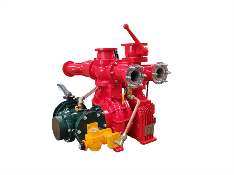
الـ مضخة إطفاء الشاحنة المثبتة CB10/60-RS تتكون من مضخة طرد مركزي منخفضة الضغط أحادية المرحلة، ومضخة تفريغ مزدوجة المكبس، وجهاز فصل تلقائي للقابض الكهرومغناطيسي، ومُضاعِف سرعة، وخط أنابيب مخرج وصمام إغلاق، وخط أنابيب مدخل. ♦ الهيكل الرئيسي والوظيفة (1) مضخة طرد مركزي منخفضة الضغط أحادية المرحلة: تتكون من غطاء المضخة، وهيكل المضخة، ودافع المرحلة الأولى، وعمود المضخة، وتوفر الضغط المقنن والتدفق المقنن. (2) مُضاعِف السرعة: تبلغ نسبة زيادة السرعة التقليدية لمُضاعِف سرعة مضخة الإطفاء المركبة على مركبة CB10/60-RS مقدار 1.440. (3) مضخة تفريغ مزدوجة المكبس: تتكون بشكل رئيسي من مكبس، وهيكل المضخة، وعمود المضخة، وعجلة لا مركزية. تُركَّب على العجلة اللامركزية قضيب توجيه المكبس وغطاء فولاذي لهيكل المضخة. تُركَّب صمامات المدخل والمخرج على طرفي مضخة المكبس. عند تعشيق القابض الكهرومغناطيسي، تبدأ مضخة المكبس في العمل. أثناء التشغيل، تؤدي الحركة اللامركزية للعجلة اللامركزية إلى حركة المكبس ذهابًا وإيابًا، مما يؤدي تدريجيًا إلى طرد الهواء من المضخة وخط الأنابيب، وبالتالي تحسين جودة الهواء. يتم إنشاء فراغ داخل التجويف لتحقيق الغرض من سحب الماء. 1. صمام إغلاق المخرج (4 قطع)؛ 2. أنابيب مياه المخرج اليمنى واليسرى؛ 3. موصل مياه رجوع تبريد علبة التروس؛ 4. موصل مقياس الضغط؛ 5. صمام عدم رجوع المخرج؛ 6. شفة مدفع المياه؛ 7. مفتاح ضغط المياه؛ 8. موصل مياه رجوع ضغط تبريد مأخذ القدرة PTO؛ 9. شفة خزان المياه الخلفي؛ 10. صمام كروي لخزان المياه الخلفي؛ 11. علبة التروس؛ 12. القابض الكهرومغناطيسي والأسلاك؛ 13. مضخة التحضير بالمكبس؛ 14. موصل مقياس الفراغ؛ 15. موصل التحضير بالفراغ؛ 16. واجهة أنبوب المدخل؛ 17. أنبوب المدخل رباعي الاتجاهات؛ 18. صمام تصريف مضخة المياه؛ 19. أنبوب مياه رجوع ضغط تبريد علبة التروس؛ 20. أنبوب مياه مدخل ضغط تبريد علبة التروس؛ 21. صمام مستوى زيت تشحيم علبة التروس؛ 22. شفة الوصلة؛ 23. سير القيادة؛ 24. موصل ملولب لمياه ضغط جهاز خلط الرغوة (غير متوفر في شاحنات صهاريج المياه)؛ 25. واجهة جهاز خلط الرغوة؛ 26. موصل مياه مخرج ضغط تبريد مأخذ القدرة PTO؛ 27. مضخة إطفاء المركبة CB10/60؛ 28. موصل مياه مخرج ضغط تبريد علبة التروس؛ 29. صمام فراشة المدخل الخلفي (4) خط أنابيب مخرج المياه منخفض الضغط وصمام الإغلاق:يتكون من صمام فحص مخرج المياه منخفض الضغط، وأنابيب مخرج المياه اليمنى واليسرى، وأربعة أنابيب مخرج مياه، وأربعة صمامات إغلاق لمخرج المياه. (5) خط أنابيب مدخل المياه المركب في الخلف:يتكون من أنبوب مدخل رباعي الاتجاهات، وشبكة ترشيح للمدخل، وموصل مدخل خارجي، وعلى جانبي أنبوب المدخل رباعي الاتجاهات يوجد في الجانب الأيمن منفذ لتركيب جهاز مزج الرغوة، بينما يجهز الجانب الأيسر بكوع مدخل خلفي دوّار، وصمام فراشة مقاس 150 مم، وشفة قابلة للحام. ♦المواصفات الطراز قطر المدخل (مم) قطر المخرج (مم) أقصى فراغ (كيلوباسكال) انخفاض الفراغ خلال دقيقة واحدة (ميغاباسكال) زمن عمق الشفط 7 م (ثانية) CB10/60-RS Φ150 Φ80X4 ≥85 ≤2.6 ≤50 الطراز ظروف التشغيل عمق الشفط (م) معدل التدفق (لتر/ثانية) الضغط (ميغاباسكال) سرعة دوران العمود (دورة/دقيقة) قدرة العمود (كيلوواط) أقصى ضغط تشغيل (ميغاباسكال) CB10/60-RS 1 3 60 1.0 3200±50 99.71 1.082 2 42 1.3 3528+50 109.18 - 3 7 30 1.0 332650 - - ♦ التشغيل 1. الأعمال التحضيرية قبل التشغيل (1) يجب إغلاق جميع صمامات التصريف الموجودة على المضخة؛ (2) با...
تفاصيل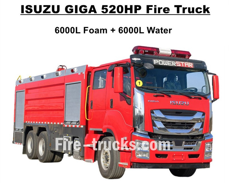
جودة عالية جدًا شاحنات إطفاء ISUZU GIGAمصدّرة إلى غرب أفريقيا بوركينا فاسو، والتي تم تصميمها اعتمادًا على هيكل شاحنة ISUZU GIGA VC66 الثقيلة 6×4، وتتبنى كابينة GIGA VC66 الجديدة، ومقعد تعليق هوائي قياسي ونظام تكييف هواء لتوفير قيادة مريحة. الشاحنة مزودة بمحرك ديزل بتقنية ISUZU اليابانية طراز 6WG1-TCG62 بقدرة 520 حصانًا، ويمكن أن يكون حجم الانبعاث 15681 سم³، ومتوافق للعمل مع ناقل حركة يدوي FAST بـ 12 سرعة، مع استهلاك وقود منخفض جدًا، وإطارات أمامية قياس 385/80R22.5 وخلفية قياس 315/80R22.5 بشكل قياسي، بإجمالي 10+1 وحدات. تشمل مجموعة الهيكل العلوي خزان مياه بسعة 6000 لتر وخزان رغوة بسعة 6000 لتر، وجميعها مصنوعة من الفولاذ المقاوم للصدأ #304، متينة لخدمة طويلة العمر. تعمل بشكل متوافق مع مضخة إطفاء فائقة القوة مخصصة CB10/140 بمعدل تدفق فعال 140 لتر/ثانية، ومزودة بمضختي إطفاء مزدوجتين أعلى مجموعة جسم الخزان، طراز PL8/64 وبمعدل تدفق فعال 64 لتر/ثانية. محرك إطفاء Isuzu GIGA بقدرة 520 حصانًامزود بجميع معدات مكافحة الحرائق الضرورية، وهو محرك إطفاء مثالي لإخماد الحرائق وإنقاذ الأشخاص، ويُستخدم على نطاق واسع في سوق بوركينا فاسو. شاحنة إطفاء خزان رغوة ISUZU GIGA بقدرة 520 حصانًا وسعة 14,000 لتر مصنع CS TRUCKS هو مصنع محترف في مجال الشاحنات،ويضمن أن جميع المنتجات جديدة تمامًا وعالية الجودة. ميزات شاحنة إطفاء ISUZU: الاسم محرك إطفاء ISUZU GIGA بمضخة رغوة سعة 12000 لتر الكابينة GIGA VC66 المحرك 6WG1-TCG62 بقدرة 520 حصانًا وحجم انبعاث 15681 سم³ ناقل الحركة FAST بـ 12 سرعة قاعدة العجلات 4600+1370 مم الإطار الأمامي: 385/80R22.5 (قطعتان) الخلفي: 315/80R22.5 (8 قطع) الخزان خزان رغوة بسعة 6000 لتر (فولاذ مقاوم للصدأ #304) خزان مياه بسعة 6000 لتر (فولاذ مقاوم للصدأ #304) مضخة الإطفاء CB10/140 بمعدل تدفق 140 لتر/ثانية مدفع الإطفاء الأمامي: PL8/64 بمعدل تدفق 64 لتر/ثانية الخلفي: PL8/64 بمعدل تدفق 64 لتر/ثانية المعدات مجموعة كاملة من معدات مكافحة الحرائق حسب التخصيص كيفية تشغيل محرك
تفاصيل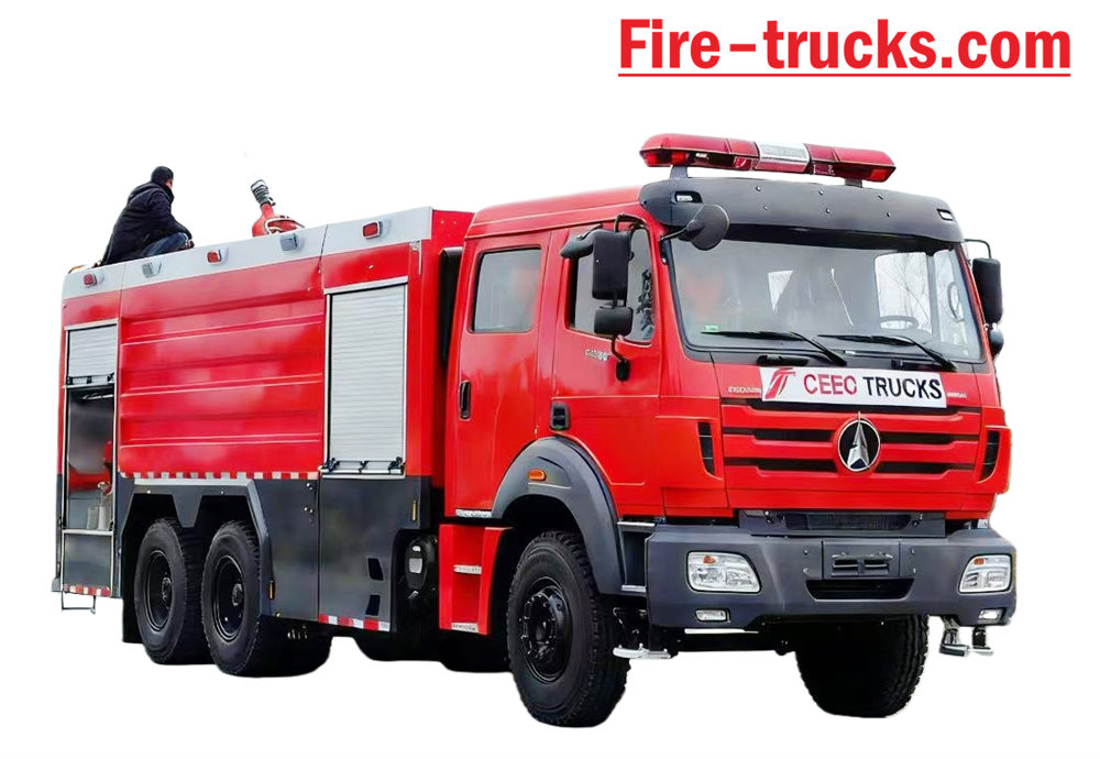
بيبن شاحنة إطفاء مبنية على هيكل شاحنة بيبن 2638 من النوع الثاني، طراز 6*4، بمقود يساري، وهيكل يمكن أن تصل السعة إلى 12000 لتر، بما في ذلك صهريج مياه بسعة 10000 لتر وخزان رغوة بسعة 2000 لتر. بيبن 2638 - فرق الإنقاذ من الحرائق شاحنة مجهزة بمضخة إطفاء حريق XIONGZHEN CB10/60 وجهاز مراقبة حريق PL8/48، مما يجعلها ملائمة للغاية لـ للاستخدام اليومي. يُستخدم بشكل أساسي في مشاريع مكافحة الحرائق في أي منطقة تحتاج إلى ذلك. صُممت المركبة لتعتمد كلياً على مزايا هيكل شاحنة ماركة بيبن الأصلي، تم مراعاة سهولة استخدام المنتج وموثوقيته بشكل كامل، بالإضافة إلى الهيكل المصمم حديثًا. المادة المستخدمة هي فولاذ كربوني ذو معايير دولية مطلي بطبقة مقاومة للتآكل وفولاذ مقاوم للصدأ، وهو يمكن أن يكون فعالاً في تجنب الصدأ وإطالة عمر الخدمة. شاحنة إطفاء بيبن 6x4 مجهزة بنظام نقل الحركة ساندويتش، ومضخة إطفاء، وجهاز مراقبة الحريق، وغرفة طاقم، وخرطوم مياه صندوق، غرفة مضخات، ناقلة مسحوق جاف ونظام نيتروجين، متوافق مع بكرة خرطوم خط الأنابيب، الإنجليزية صندوق التحكم في الإصدار، وخط أنابيب المدخل والمخرج، وسلم التسلق الخلفي، ومصباح الوسادة العلوي، وجميع الضروريات معدات مكافحة الحرائق. مقصورة مزدوجة الصفوف مصممة خصيصًا بمقاعد 2+4 توفر تجربة قيادة ممتعة. لذلك، ال تُعد هذه المركبة شاحنة إطفاء مثالية، خاصةً لمشاريع مكافحة الحرائق. [if gte mso 9]> عادي 0 7.8 磅 0 2 خطأ false false EN-US ZH-CN X-NONE
تفاصيل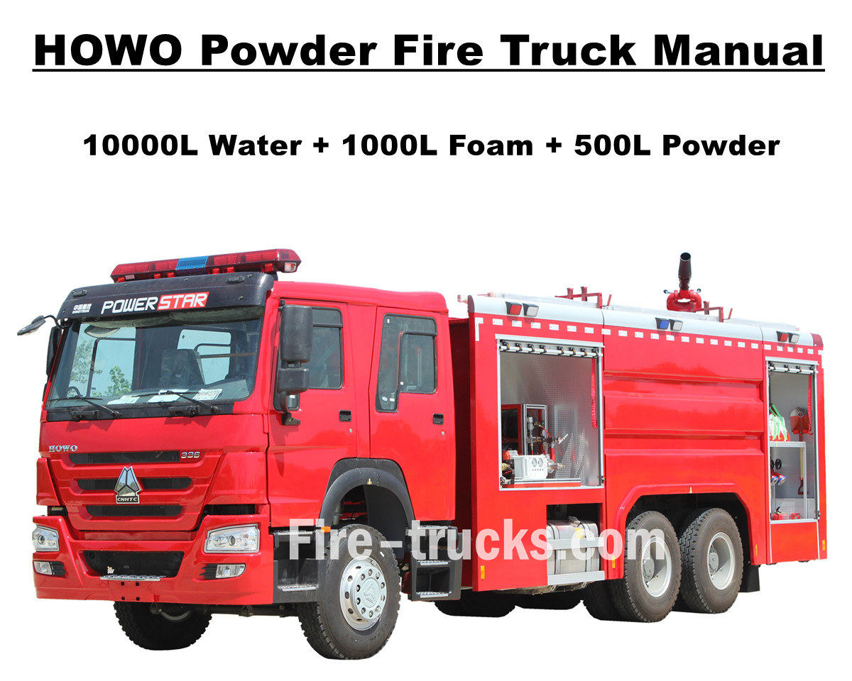
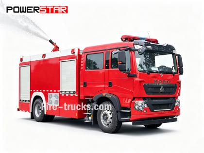
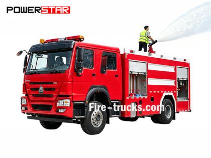
قام عميل من موريتانيا بأفريقيا بشراء 4 وحدات إجمالاً محرك إطفاء المضخة ساينو تراك HOWO من إنتاج شركة باور ستار تراكس، وتُستخدم في العاصمة نواكشوط. تُعرف شاحنة الإطفاء أيضًا باسم محرك الإطفاء أو مضخة الإطفاء، وهي مركبة مصممة ومصنعة لتلبية احتياجات مشاريع إطفاء الحرائق وإنقاذ الأفراد على مستوى العالم. تتميز الشاحنة بكابينة مزدوجة مخصصة لنقل رجال الإطفاء، بالإضافة إلى معدات وأدوات متنوعة لمكافحة الحرائق والإنقاذ. ولضمان كفاءة عمل شاحنات إطفاء هوو، قمنا بتخصيصها بسلالم من سبائك الألومنيوم، وخزانات لتخزين رغوة الماء ومسحوق الإطفاء الجاف، ومضخة إطفاء فعالة من طراز CB10/60 مزودة بمدفع حريق PL8/48، مما يتيح مدى رش فعال يصل إلى أكثر من 70 مترًا، وبكرة خرطوم إطفاء مزودة بمسدس لإطفاء الحرائق عن بُعد، وجهاز تنفس مزود بقناع، وملابس واقية، وأدوات إنقاذ، وحقيبة إسعافات أولية، وغيرها. جميع خدمات شاحنات إطفاء هوو مصممة لضمان عملها بكفاءة وموثوقية. لضمان استخدام عملاء موريتانيا لسيارات إطفاء الحرائق من طراز HOWO بسهولة وكفاءة أكبر، تم تزويد جميع الشاحنات بمجموعات كاملة من كتالوجات الخدمة باللغة الإنجليزية، بما في ذلك دليل المستخدم لإرشادات التشغيل، ودليل الشاحنة، ودليل قطع الغيار للاستخدام والصيانة. شاحنة إطفاء سينوتروك هاوو 14000 لتر مزودة بمضخة مسحوق مصنع باورستار شركة تصنيع متخصصة في مجال الشاحنات، نضمن أن جميع المنتجات جديدة تمامًا وعالية الجودة. » Ⅰ. مزايا شاحنة إطفاء HOWO: ★ محرك ديزل قوي من نوع WEICHAI بقوة 247 كيلوواط / 336 حصان، يقطع مسافة 100,000 كيلومتر بدون مشاكل. ★ مقصورة سينوتروك هاوو الكلاسيكية HW76، تصميم أوروبي ★ مضخة حريق CB10/60 مثبتة، معدل تدفق 60 لتر/ثانية، موثوقة للغاية ★ مدفع مياه PL8/48 مثبت في الأعلى، خدمة متينة ★ ٥٠٠ لتر من المسحوق الجاف مع زجاجة نيتروجين، مزودة بصمامات للتحكم في الهواء ★ نظام تحكم متكامل للرغوة والبودرة، مع لوحة تحكم في ال�
تفاصيل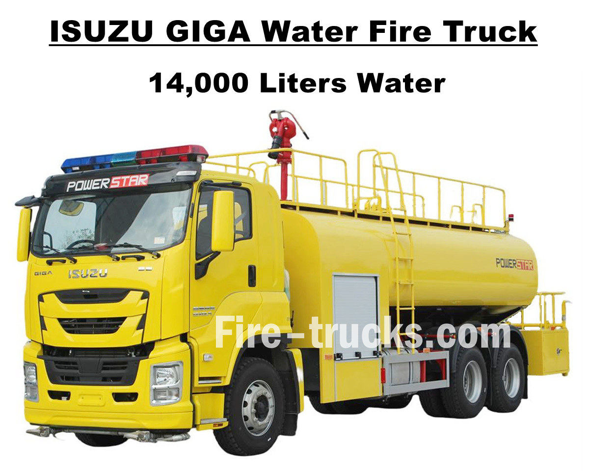
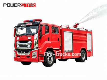
العميل الجنوب أمريكي السيد جوزيف من هندوراس، الذي اشترى وحدة واحدة شاحنة إطفاء حرائق إيسوزو جيجا VC66 بسعة 14000 لتر (3700 جالون) من الماء من شاحنات POWERSTAR، صُممت هذه الشاحنة على هيكل شاحنة إيسوزو جيجا اليابانية الثقيلة 6x4، وهي مزودة بمحرك ديزل طراز 6UZ1-TCG60 بقوة 280 كيلوواط/380 حصان، وهو محرك سداسي الأسطوانات، رباعي الأشواط، مبرد بالماء، مزود بشاحن توربيني ومبرد داخلي، بسعة 9839 مل. وتعمل الشاحنة مع ناقل حركة يدوي FAST ذي 12 سرعة وفقًا للمعايير الدولية، 12 سرعة أمامية وسرعتين خلفيتين، مما يقلل من استهلاك الوقود بشكل فعال. كما أنها مزودة بـ 13 إطارًا فولاذيًا من طراز 12R22.5، بما في ذلك إطار احتياطي، مما يجعلها مناسبة لمختلف أنواع الطرق، بما في ذلك تسلق الجبال. ويمكن اختيار قاعدة عجلات متعددة بأطوال 4600+1370 مم. خدمة مصممة بشكل مناسب ومريح لمشروع إطفاء الحرائق في مناطق متعددة. تعتمد شاحنة إطفاء الحرائق إيسوزو جيجا، المزودة بخزان مياه سعة 3700 جالون، كليًا على تقنية إيسوزو اليابانية، وهيكل شاحنة جيجا VC66 الأصلي المجهز بنظام تكييف هواء مع وظيفة التدفئة والتبريد لتوفير قيادة مريحة. الشاحنة مزودة بخزان مياه مصنوع بالكامل من الفولاذ المقاوم للصدأ SS304، بسعة 14000 لتر (3700 جالون)، ومجهزة بمضخة إطفاء CB10/60 صينية الصنع، وجهاز مراقبة حريق PS8/50 مثبت أعلى الخزان، بالإضافة إلى مجموعة كاملة من معدات الإنقاذ والإطفاء، وطلاء أصفر ليموني مخصص للشاحنة بأكملها، مما يجعلها مركبة مثالية لمشاريع إطفاء الحرائق في شوارع وأحياء هندوراس. كما تأتي الشاحنة مع دليل خدمة كامل باللغة الإنجليزية، يشمل دليل المستخدم للتشغيل، ودليل استخدام شاحنة جيجا، ودليل قطع الغيار للصيانة. شاحنة إطفاء حرائق مزودة بمضخة مياه من طراز إيسوزو جيجا سعة 14000 لتر مصنع باورزتار هي الشركة المصنعة المهنية في مجال الشاحنات، نضمن أن جميع المنتجات جديدة تمامًا وعالية الجودة. » ١. مزايا شاحنة إطفاء المياه من إيسوزو: ★ محرك ديزل قوي 6WG1 بقوة 280 كيلوواط / 380 حصان، يقطع مسافة 100,000 كم بدون مشاكل. ★ مقصورة ISUZU VC66 الجديدة ذات التصميم الأوروبي ★ مضخة حريق CB10/60 مثبتة، معدل تدفق 60 لتر/ثانية، موثوقة للغاية ★ مدفع مياه PS8/50 مثبت في الأعلى، خدمة متينة ★ نظام تحكم متكامل، مع لوحة تحكم جانبية ★ لوحة زيتية صفراء ليمونية مصممة خصيصًا، لامعة وجميلة مضخة حريق CB10/60 نموذج : CB10/60 ضغط : 1.0 ميجا باسكال أقصى ضغط عمل : 1.232 ميجا باسكال معدل التدفق : 60 لتر/ثانية عند 1.0 ميجا باسكال، سرعة 3286±50 دورة/دقيقة، قوة 102 كيلو وات، عمق الشفط 3 أمتار 42 لتر/ثانية عند 1.3 ميجا باسكال، سرعة 3519±50 دورة/دقيقة، قوة 106 كيلو وات، عمق الشفط 3 أمتار 30 لتر/ثانية عند 1.0 ميجا باسكال، سرعة 3120±50 دورة/دقيقة، قوة 73 كيلو وات، عمق الشفط 7 أمتار نسبة السرعة : 1:1.44 جهاز مراقبة الحرائق PS8/50 نموذج : PS8/50 ضغط : 0.8 ميجا باسكال نطاق العمل : ماء ≥ 65 م الدوران الرأسي : -45 درجة ~ +70 درجة الدوران الأفقي : 0° ~ 360° معدل التدفق : 50 ل/ث » 2/2 . رسم شاحنة إطفاء الحرائق إيسوزو: صُممت شاحنة إطفاء الحرائق ISUZU GIGA VC66 14000L المزودة بخزان مياه، وصُدّرت إلى هندوراس في أمريكا الجنوبية. الشاحنة مزودة بخزان مياه سعة 3700 جالون، مصنوع بالكامل من الفولاذ المقاوم للصدأ SS304، بسماكة تصل إلى 5 مم. تحتوي الشاحنة على منصة خلفية صغيرة مخصصة وصندوق أدوات. بين كابينة GIGA وخزان المياه، توجد غرفة مضخة مزودة بمضخة مياه CB10/6...
تفاصيل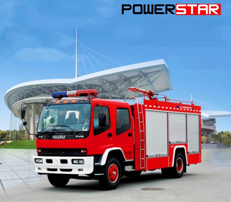
تصنع شركة Powerstar Trucks مركبات مخصصة للاستجابة للطوارئ و شاحنات الإطفاء على مدى عدة سنوات، رسخت شركة باورزتار تراكس للاستجابة للطوارئ إرثها كشركة رائدة في تصنيع خطوط إنتاج كاملة لأجهزة الإطفاء المخصصة بخبرة في سيارات إطفاء تعمل برغوة المياه و مركبة إطفاء إنقاذ بناءً على الإرث الذي يثق به رجال الإطفاء، تقدم شاحنات باورزتار حلولاً مرنة واستراتيجية ومتخصصة لتلبية كل احتياجات إدارة الإطفاء الفريدة، مع وضع المستجيبين الأوائل في المقام الأول 120 وحدة من شاحنات الإنقاذ والإطفاء جاهزة للتسليم تصدير 65 وحدة من شاحنات الإطفاء والإنقاذ إلى شرطة أوغندا شاحنات إطفاء المياه مركبة إطفاء رغوية تُصنف شاحنات الإطفاء بشكل أساسي إلى أربع فئات وفقًا لوظيفتها: شاحنات إطفاء الحرائق، وشاحنات سلم جوي، وشاحنات إطفاء للأغراض الخاصة، وشاحنات إطفاء للدعم اللوجستي ٠١، شاحنات إطفاء الحرائق هي القوة الرئيسية لإطفاء الحرائق بشكل مباشر، بما في ذلك: * **سيارات إطفاء خزان المياه:** مجهزة بخزان مياه ومضخة خاصة بها، وهي مناسبة لإطفاء الحرائق العامة. * **شاحنات إطفاء الرغوة:** مصممة خصيصًا لإطفاء الحرائق التي تنطوي على سوائل قابلة للاشتعال مثل الزيت. * **شاحنات إطفاء المسحوق الجاف:** مناسبة لإطفاء حرائق الغاز والكهرباء. * **شاحنات إطفاء ثاني أكسيد الكربون:** تستخدم لحماية المعدات القيمة والأدوات الدقيقة. * **شاحنات الاستخدام المشترك للرغوة والمسحوق الجاف:** يمكنها استخدام كلا من عوامل الإطفاء في وقت واحد، مع مجموعة واسعة من التطبيقات. ٠٢، شاحنات الإطفاء ذات السلم الجوي تُستخدم للإنقاذ ومكافحة الحرائق في المباني الشاهقة، بما في ذلك بشكل أساسي: * **سيارات الإطفاء ذات السلم:** مجهزة بسلم تلسكوبي، قادرة على إنقاذ الأشخاص وإطفاء الحرائق على المرتفعات. * **شاحنات مكافحة الحرائق ذات الرش الجوي:** تستخدم ذراعًا يتم التحكم فيها عن بعد لرش مواد الإطفاء على مسافات طويلة. * **شاحنات الإطف�
تفاصيل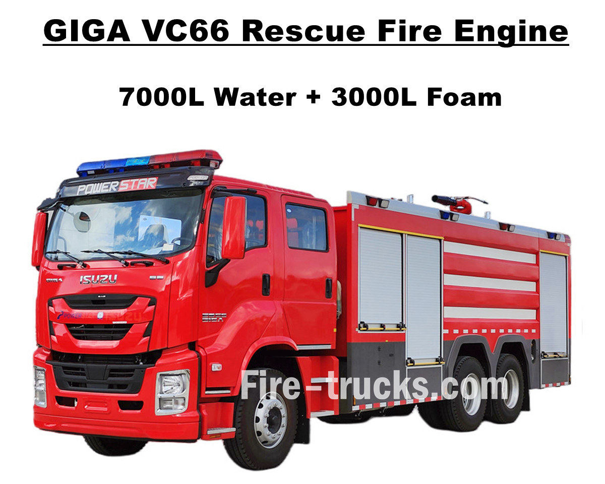
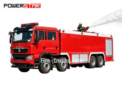
اشترى عملاء مانيلا الفلبينيون شاحنة إطفاء حرائق ثقيلة Isuzu GIGA VC66 من شاحنات POWERSTAR، وهي مجهزة بمحرك ديزل ياباني من نوع ISUZU 6WG1-TCG61 بقوة 338 كيلوواط / 460 حصان، وهو محرك سداسي الأسطوانات، رباعي الأشواط، مبرد بالماء، مزود بشاحن توربيني ومبرد داخلي، بسعة تصميم قياسية تبلغ 15681 سم مكعب، ويعمل مع ناقل حركة يدوي FAST ذي 12 سرعة وفقًا للمعايير الدولية، 12 سرعة للأمام وسرعتين للخلف، مما يوفر استهلاكًا منخفضًا جدًا للوقود، ومجهزة بـ 13 إطارًا بدون أنابيب من طراز 315/80R22.5، بما في ذلك إطار احتياطي واحد، مما يجعلها مناسبة جدًا لأنواع متعددة من ظروف الطرق. وتُستخدم هذه الشاحنة في مشاريع إطفاء الحرائق في مناطق متعددة. تعتمد الشاحنة كليًا على هيكل شاحنة إيسوزو جيجا VC66 الأصلي، مع تعديل كابينة جيجا ذات صفين من المقاعد الأمامية (2+1) ومقاعد خلفية (4 مقاعد لأجهزة التنفس). تحتوي الكابينة على مكيف هواء مزود بخاصيتي التدفئة والتبريد لتوفير قيادة مريحة. كما زُودت الشاحنة بهيكل صهريج مصنوع بالكامل من الفولاذ المقاوم للصدأ SS304، ومجهزة بمضخة إطفاء من طراز XIONGZHEN CB10/60 صينية الصنع في غرفة المضخات الخلفية، بالإضافة إلى جهاز مراقبة حريق WESTER PL8/48 مثبت أعلى هيكل الصهريج، ومجموعة كاملة من معدات الإنقاذ والإطفاء، مما يجعلها مركبة مثالية لمشاريع إطفاء الحرائق في شوارع مانيلا ومجتمعاتها. كما تُرفق الشاحنة بكتالوج خدمة كامل باللغة الإنجليزية، يشمل دليل المستخدم للتشغيل، ودليل استخدام شاحنة جيجا، ودليل قطع الغيار للصيانة. شاحنة إطفاء حرائق إيسوزو سعة 7000 لتر ماء و3000 لتر رغوة مصنع باورزتار هي الشركة المصنعة المهنية في مجال الشاحنات، نضمن أن جميع المنتجات جديدة تمامًا وعالية الجودة. » ١. شاحنة إطفاء إيسوزو ٦WG١ الميزات الرئيسية: ★ محرك ديزل قوي 6WG1 بقوة 338 كيلو وات / 460 حصان، 100000 كم دون مشاكل. ★ مقصورة ISUZU VC66 الجديدة ذات التصميم الأوروبي ★ كابينة صف مزدوج، مع 4 مقاعد خلفية مزودة بجهاز تنفس ذاتي ★ مضخة حريق مثبتة CB10/60-XZ، معدل تدفق 60 لتر/ثانية، موثوقة للغاية ★ مدفع ناري من الرغوة PL8/48 مثبت في الأعلى، خدمة متينة ★ نظام تحكم متكامل، مع لوحة في الخلف مضخة حريق CB10/60-XZ نموذج : CB10/60-XZ ضغط : 1.0 ميجا باسكال أقصى ضغط عمل : 1.232 ميجا باسكال معدل التدفق : 60 لتر/ثانية عند 1.0 ميجا باسكال، سرعة 3286±50 دورة/دقيقة، قوة 102 كيلو وات، عمق الشفط 3 أمتار 42 لتر/ثانية عند 1.3 ميجا باسكال، سرعة 3519±50 دورة/دقيقة، قوة 106 كيلو وات، عمق الشفط 3 أمتار 30 لتر/ثانية عند 1.0 ميجا باسكال، سرعة 3120±50 دورة/دقيقة، قوة 73 كيلو وات، عمق الشفط 7 أمتار نسبة السرعة : 1:1.44 جهاز مراقبة الحرائق PL8/48 نموذج : PL8/48 ضغط : 0.8 ميجا باسكال نطاق العمل : رغوة ≥ 70 مترًا وماء ≥ 60 مترًا الدوران الرأسي : -45 درجة ~ +70 درجة الدوران الأفقي : 0° ~ 360° معدل التدفق : 48 ل/ث » 2/2 . الرسم الفني لشاحنة إطفاء الحرائق إيسوزو: شاحنة إطفاء ISUZU GIGA VC66 مزودة بصهريج مياه ورغوة، ومتوافقة مع جهاز مراقبة الحرائق XIONGZHEN CB10/60 وجهاز مراقبة الحرائق Wester PL8/48، وهي خدمة شاحنة إنقاذ من الحرائق المثالية للفلبين مانيلا. » Ⅲ . نظرة عامة على سيارة إطفاء GIGA: شاحنات إطفاء الحرائق الثقيلة الجديدة من طراز ISUZU GIGA VC66 هي الخيار الأمثل لإطفاء الحرائق وإنقاذ الأشخاص. تتميز بتصميمها المتطور وجودة أدائها الموثوقة. ----- مواد الناقلة : الفولاذ الكربوني، الفولاذ المقاوم للصدأ، سبا...
تفاصيل
بيع المصنع شاحنة إطفاء إيسوزو رباعية الدفع للطرق الوعرة تستخدم شاحنة إطفاء الحرائق إيسوزو بيك أب هيكل إيسوزو تاغا رباعي الدفع، وتضم نظام طاقة ممتازًا لتجاوز جميع أنواع الطرق الوعرة. وهي مجهزة بخزان مياه مصنوع بالكامل من الفولاذ المقاوم للصدأ SS304، بسعة 500 لتر وخزان رغوة بسعة 100 لتر، بالإضافة إلى مضخة إطفاء حريق احترافية مستقلة JBQ4.5/9 مثبتة في غرفة المضخة الخلفية، تتميز بمدى رش طويل ولوحة تحكم اختيارية. كما توفر الشاحنة مجموعة متنوعة من التكوينات الاختيارية لتلبية مختلف الاحتياجات، ومجهزة بمدفع مياه PS20 في الأعلى. توفر شاحنة إطفاء الحرائق إيسوزو بيك أب بقوة 143 حصانًا ضمانًا قويًا لسلامة الحريق، وتتميز بأداء ومرونة فائقة. توفر الكابينة الأصلية ذات الصفين مساحة كافية وراحة عالية لتحميل معدات الإطفاء والحفاظ على أداء قيادة ممتاز. تتسع الكابينة لخمسة رجال إطفاء، وهي مجهزة بتكييف هواء لضمان راحة السائق في جميع الظروف الجوية. جميعها تضمن أن تكون سيارة إطفاء ISUZU 600L الرغوية مثالية لخدمة الإنقاذ من الحرائق في السوق الألبانية. كما أن دليل المستخدم مُجهّز لضمان التشغيل الآمن والعمل. » ١. الميزات الرئيسية لشاحنة إطفاء بيك أب إيسوزو: ★ محرك 4KH1 قوي بقوة 105 كيلو وات / 143 حصان، 100000 كم دون مشاكل. ★ مقصورة شاحنة ISUZU TAGA الجديدة، تصميم أوروبي ★ كابينة مزدوجة أصلية، مناسبة لخمسة رجال إطفاء ★ مضخة حريق JBQ4.5/9 مستقلة، موثوقة للغاية ★ مدفع ناري PS8/20 مثبت في الأعلى، خدمة متينة » 2. نظرة عامة على عطاء إطفاء الحرائق: شاحنة إطفاء الحرائق إيسوزو رباعية الدفع للطرق الوعرة، مزودة برغوة الماء، هي شاحنة إنقاذ حرائق لجميع التضاريس، تخدم مناطق متعددة، بما في ذلك الأحياء السكنية والغابات والمصانع وغيرها. بفضل قدرتها على السير على الطرق الوعرة ومظهرها الضيق، يمكن لهذه الشاحنة الصغيرة من إيسوزو إنجاز مهام متعددة بنجاح. ولجعل شاحنات الإطفاء لدينا أكثر ملاءمة، نقدم خيارات متنوعة لعملائنا. ----- مواد الناقلة : الفولاذ الكربوني، الفولاذ المقاوم للصدأ، سبائك الألومنيوم، مادة PP ----- مضخة حريق : بناءً على جسم الناقلة ومسافة النفث، اختياري أمريكي دارلي ماركة ----- خياري: خط الأنابيب، بكرة الخرطوم، سلم الألومنيوم، نموذج المفصل (الصيني، الأوروبي، الأمريكي) » Ⅲ. المظهر الجذاب: شاحنة إطفاء إيسوزو 4x4 ذات الدفع الرباعي قوية وسريعة الاستجابة، تصل إلى موقع الحريق بسرعة، وتجتاز التضاريس الوعرة بسهولة. يتميز مدفع الإطفاء العلوي بمدى بعيد وتدفق عالٍ، كما أن خرطوم الإطفاء الطويل (50 مترًا) المزود بمدفع قادر على إصابة مصدر الحريق بدقة وتغطيته وعزله بكفاءة. هذه الشاحنات مجهزة بمجموعة كاملة من أدوات الإنقاذ. تتوفر تكتيكات تكيفية تناسب مختلف أنواع الحرائق، كالمباني والغابات وخزانات النفط وتسربات المواد الكيميائية الخطرة، مما يتيح استخدامها في عمليات إطفاء سريعة أو دقيقة. وتحظى شاحنات إطفاء إيسوزو من هذا النوع بأداء ممتاز وخدمة موثوقة في ألبانيا. شاحنة بيك اب ايسوزو 4x4 مقصورة قيادة مريحة في شاحنة ايسوزو دليل مستخدم شاحنة إطفاء إيسوزو وكتالوج قطع الغيار شاحنة إطفاء إيسوزو مزودة بنظام إضاءة غرفة مضخة شاحنة إطفاء بيك أب إيسوزو 4x4 شاحنة إطفاء بيك اب إيسوزو مضخة مستقلة منظر خلفي لشاحنة الإطفاء مكون خط أنابيب إطفاء شاحنة بيك آب إيسوزو 4x4 شاحنة إطفاء من نوع إيسوزو مزودة ببكرة خرطوم بطول 50 مترًا أدوات الإنقاذ في شاحنة إطفاء الحرائق من إيسوزو شاحنة إطفاء إيسوزو 4x4 مزودة بجهاز مراقبة ا...
تفاصيل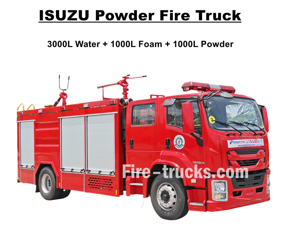
تم تصميمها وتصنيعها حديثًا شاحنة إطفاء حرائق ISUZU GIGA 4X برغوة مائية ومسحوق جاف محرك إطفاء إيسوزو عالي الأداء يُصدّر إلى نيجيريا، لاغوس، مزود بمحرك ديزل 4HK1-TCG60 بقوة 150 كيلوواط/205 أحصنة، وسعة انبعاثات 5193 سم مكعب، متوافق مع ناقل حركة يدوي MLD بستة تحولات، بست سرعات أمامية وسرعة خلفية واحدة، مما يوفر قوة دفع عالية واستهلاك وقود أقل، ويضمن استجابة أسرع وقيادة مستقرة. محرك إطفاء إيسوزو 5000L مزود بمجموعة هيكل صهريج سعة 5000 لتر، تتضمن صهريج مياه سعة 3000 لتر، وصهريج رغوة سعة 1000 لتر، وصهريج مسحوق جاف سعة 1000 لتر. جميع الصهاريج مصنوعة من الفولاذ المقاوم للصدأ SS304، بتصميم مربع الشكل مع حاجز داخلي، وغطاء فتحة صرف DN500 وقفل للأمان. شاحنات إطفاء مضخات مسحوق إيسوزو مُجهزة بمضخة إطفاء CB10/40، بمعدل تدفق فعال يبلغ 40 لترًا في الثانية، ومتوافقة مع نظام مراقبة إطفاء رغوة الماء PL8/32، بمعدل تدفق فعال لرغوة الماء الممزوجة 32 لترًا في الثانية. تعمل الشاحنة مع العديد من معدات الإنقاذ، مما يجعل مركبة إطفاء ISUZU giga 4X مركبة مثالية لإطفاء الحرائق وإنقاذ الأشخاص، وتعمل بكفاءة في منطقة لاغوس النيجيرية. كما أنها مُجهزة بصهريج مسحوق جاف من سلسلة R25-006، بضغط مُصمم يبلغ 1.55 ميجا باسكال وسعة مُصممة تبلغ 1000 لتر، ومُجهزة أيضًا بزجاجات نيتروجين فعالة للاستخدام. ولضمان كفاءة تشغيل وأداء شاحنات إطفاء إيسوزو، يُقدم الدليل المرفق أدناه إرشادات للعملاء في نيجيريا حول المعدات. ♦ شاحنة إطفاء حرائق مسحوق جاف ISUZU GIGA ♦ شاحنة إطفاء مسحوق جاف POWERSTAR ISUZU يدوية للتصدير إلى نيجيريا لوحة تحكم شاحنات إطفاء الحرائق إيسوزو مكون تفصيلي لشاحنة إطفاء الحرائق إيسوزو » ١. الميزات الرئيسية لشاحنة إطفاء إيسوزو: ★ محرك 4HK1 قوي بقوة 205 حصان، 100000 كم دون مشاكل. ★ ISUZU GIGA موديل جديد 4X كابينة، تصميم أوروبي ★ محور تكنولوجيا ISUZU، مناسب للغاية لأفريقيا. ★ مضخة CB10/40 الشهيرة في الصين، موثوقة للغاية ★ مدفع ناري PL8/32 مصمم بشكل علوي ومتين ★ مجموعة مسحوق جاف، وزجاجات نيتروجين متطابقة » Ⅱ.ISUZU شركة تصنيع عربات إطفاء الحرائق: شاحنة إطفاء الحرائق إيسوزو جيجا برغوة الماء والمسحوق الجاف هي شاحنة إطفاء رئيسية متوسطة الحجم، تعمل بكامل طاقتها، تجمع بين قدرة عالية على الحركة، واحتياطيات وافرة من مواد الإطفاء، وقدرات قتالية متنوعة. أما من حيث القوة، فهي مزودة بمحرك ويتشاي مقترن بناقل حركة ساينوتروك، مما يوفر قوة هائلة وناقل حركة فعال. ----- مواد الناقلة : الفولاذ الكربوني، الفولاذ المقاوم للصدأ، سبائك الألومنيوم، مادة PP ----- مضخة حريق : بناءً على جسم الناقلة ومسافة النفث، اختياري أمريكي دارلي ماركة ----- خياري: خط الأنابيب، بكرة الخرطوم، سلم الألومنيوم، نموذج المفصل (الصيني، الأوروبي، الأمريكي) شاحنات إطفاء الإنقاذ من إيسوزو للإنتاج شاحنة إطفاء حرائق ISUZU 205HP للإنتاج شاحنة إطفاء حرائق مسحوق Isuzu GIGA 4X » Ⅲ. إيسوزو الميزات المتقدمة لمضخة الحريق: صُممت شاحنات إطفاء مسحوق الرغوة المدمجة من إيسوزو بناءً على هيكل شاحنة إيسوزو جيجا 4X، وهي مزودة بمحرك ديزل 4HK1 بقوة 205 أحصنة، ومتوافقة مع ناقل حركة MLD بستة نواقل حركة، ومُزودة بصهريج مياه وصهريج رغوة، ومضخة إطفاء CB10/40 وجهاز مراقبة حريق PL8/32. هذه الشاحنات مُجهزة بأنظمة رغوة ثنائية الاستخدام، يُمكن التبديل بين أنواع الرغوة المختلفة حسب نوع الحريق المُواجه. يُظهر أدناه ما مجموعه 10 وحدات من شاحنات إطفاء مسحوق إيسوزو التي اشت...
تفاصيل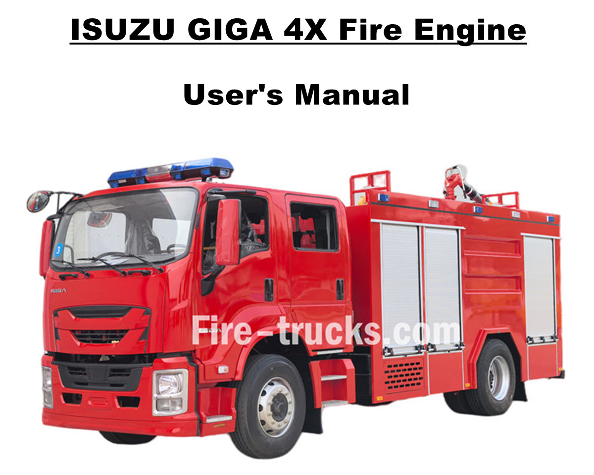
اشترى عملاء مولدوفا 6 وحدات شاحنة إطفاء وإنقاذ مطار إيسوزو جيجا 4X من شاحنات باور ستار، نوفر خدمة إطفاء حرائق في مناطق متعددة. نعتمد كليًا على هيكل شاحنة إيسوزو جيجا 4X الأصلي، ونُعدّل كابينة جيجا 4X ذات الصفين بمقعدين أماميين عاديين، وأربعة مقاعد خلفية مزودة بنظام تنفس ذاتي (SCBA). المقصورة مجهزة بتكييف هواء مع خاصية التدفئة والتبريد لقيادة مريحة. مجهزة بمحرك ديزل ISUZU الياباني 4HK1-TCG60 بقوة حصانية 151 كيلو وات / 205 حصان، وهو محرك رباعي الأسطوانات، رباعي الأشواط، مبرد بالماء، بشاحن توربيني ومبرد داخلي، سعة مصممة 5193 سم مكعب قياسي، متوافق مع ناقل الحركة اليدوي ISUZU MLD 6 shift، 6 shift تتحرك للأمام و 1 shift تتحرك للخلف، استهلاك وقود أقل للغاية، تم تركيب 7 وحدات إطارات بدون أنابيب بالكامل مع طراز 295/80R22.5، مناسب جدًا لأنواع متعددة من ظروف الطريق. شاحنة إطفاء إيسوزو سعة 5000 لتر ماء و1000 لتر رغوة مصنع باورزتار هي الشركة المصنعة المهنية في مجال الشاحنات، نضمن أن جميع المنتجات جديدة تمامًا وعالية الجودة. » 1 . تطبيقات مكافحة الحرائق: شاحنة إطفاء ISUZU GIGA 4X الجديدة، بقوة 205 حصان، مُجهزة بمجموعة كاملة من معدات مكافحة الحرائق وأدوات إنقاذ الأشخاص، وتتميز بكفاءة عالية في ضخ المياه والرغوة، ومناسبة لأعمال إطفاء الحرائق المتعددة في المدن والمصانع والمجتمعات المحلية، إلخ. تتوفر الميزات المتقدمة المفصلة أدناه: 1. شاحنة ISUZU GIGA 4X: طراز ISUZU 4HK1-TCG60 الياباني بمحرك ديزل بقوة 151 كيلوواط / 205 حصان 2. ناقلة المواد SS304: صهريج مياه مخصص سعة 5000 لتر وصهريج رغوة سعة 1000 لتر، جميعها مصنوعة من الفولاذ المقاوم للصدأ SS304 3. مضخة الحريق CB10/40: مثبتة في الخلف، مع غرفة مستقلة، ووظيفة ضخ المياه للداخل والخارج متاحة مضخة حريق CB10/40 نموذج : CB10/40 ضغط : 1.0 ميجا باسكال أقصى ضغط عمل : 1.38 ميجا باسكال معدل التدفق : معدل تدفق 40 لتر/ثانية عند ضغط 1.0 ميجا باسكال، سرعة دوران 3330±50 دورة/دقيقة، قدرة 60 كيلوواط، عمق شفط 3 أمتار 28 لتر/ثانية عند ضغط 1.3 ميجا باسكال، سرعة 3540±50 دورة/دقيقة، قدرة 59 كيلوواط، عمق شفط 3 أمتار معدل تدفق 20 لتر/ثانية عند ضغط 1.0 ميجا باسكال، سرعة دوران 3335±50 دورة/دقيقة، قدرة 42 كيلوواط، عمق شفط 7 أمتار نسبة السرعة : 1:1.542 4. جهاز مراقبة الحرائق PL8/36: نموذج تشغيل يدوي مثبت في الأعلى مع مسافة نفث متاحة تزيد عن 55 مترًا، يتميز بالكفاءة والمتانة جهاز مراقبة الحرائق PL8/36 نموذج : PL8/36 ضغط : 0.8 ميجا باسكال نطاق العمل : رغوة ≥ 60 مترًا وماء ≥ 48 مترًا الدوران الرأسي : -45 درجة ~ +70 درجة الدوران الأفقي : 0° ~ 360° معدل التدفق : 36 لتر/ثانية 5. متكامل جهاز التحكم شاحنات إطفاء الحرائق من إيسوزو مزودة بجهاز تحكم متكامل في غرفة المضخة الخلفية، مما يجعلها مريحة وذكية. » 2/2 . ميزات متقدمة لسيارة الإطفاء: شاحنة إطفاء الإنقاذ الثقيلة ISUZU GIGA 4X هي الخيار الأمثل لإطفاء الحرائق وإنقاذ الأشخاص. تتميز بتصميمها المتطور وجودة أدائها الموثوقة. ----- مواد الناقلة : الفولاذ الكربوني، الفولاذ المقاوم للصدأ، سبائك الألومنيوم، مادة PP ----- مضخة حريق : بناءً على جسم الناقلة ومسافة النفث، اختياري أمريكي دارلي ماركة ----- خياري: خط الأنابيب، بكرة الخرطوم، سلم الألومنيوم، نموذج المفصل (الصيني، الأوروبي، الأمريكي) خزانة شاحنة إطفاء الحرائق ISUZU GIGA 4X كابينة شاحنة إطفاء طراز ISUZU GIGA 4X، مزودة من الداخل بمكيف هواء وراديو AM/FM، طرا...
تفاصيل
الرجاء المتابعة، والاطلاع على آخر المستجدات، والاشتراك، ونرحب بآرائكم.

 شبكة IPv6 مدعومة

 العربية
 English
 français
 Deutsch
 русский
 italiano
 español
 português
 Nederlands
 日本語
日本語 한국의
한국의 Türkçe
 Melayu
 ไทย
ไทย Tiếng Việt
 Indonesia
  中文
中文 қазақ
қазақ Filipino
 မြန်မာ
 српски